Procedure of assembly wiring
To each page : 1 , 2 , 3 , 4 , 5 , 6 , 7 , 8 , 9 , 10 , 11 , 12 , 13
Procedure of assembly wiring (11/13)
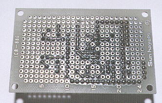
 The +5V wiring
 Desolder at 22C and 22E using solder sucker.
 Presoldering wire is attched to 22G from 22F direction. And solder at 22G.
 Pulling the wire and solder at 22C.
 Bend at 22B to 21B direction and extend to 16B.
 Solder at 17B.
 Bend the wire at 16B to 16C direction, and extend to 16E, and cut it at 16E.
 Solder the wire at 16E together with the lead of IC socket.
 Solder at 22E, 21B, 16C and 19B to the turn.
 And solder at 16D, 16B, 18B, 20B, 22B, 22D and 22F.

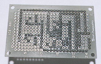
 The +12V wiring of R4 and R6
 Solder the lead of R6 at 3L.
 Solder the presoldering wire to 3L from 3K direction.
 Pulling the wire, and solder at 3B, and 3H.
 Solder with the lead of R4 at 3D.
 Bend the wire at 3A to 4A direction, and extend to 24A.
 Hold down the wire, and solder at 4A, 9A, 14A, 19A and 23A to the turn.
 Bend the wire at 24A to 24B, and extend to 24I.
 Hold down the wire, solder at 24B and 24G.
 Cut the wire at 24I.
 Solder from 3K to 3A to the turn.
 Solder from 5A to 24A to the turn.
 Solder from 24C to 24H to the turn.
 The +12V wiring of C1 and C2
 Desolder at 22K.
 Solder the presoldering wire at 22M from 22L direction.
 Hold down the wire, and solder the lead of C2 at 22K.
 Bend the wire at 22I to 23I direction, and extend to 25I.
 Hold down the wire, and solder with the lead of IC2 at 22I together, and with the lead of R4 and R6 at 24I together.
 Solder at 22L, 22J, 23I and 25I to the turn.
 Soldering of the unuse lead of IC socket
 Solder at 16H, 19F, 19G, 19H, 19I and 19J to the turn.

 Cut the leads of the IC socket.
 Attach the spacer to the printed board
 Put the spacers to four corners of the printed board. The spacers are used when the circuit is housed to the case etc. In this time they are used to prevent touching the wiring side of the printed board to desk etc.

