Procedure of assembly wiring
To each page : 1 , 2 , 3 , 4 , 5 , 6 , 7 , 8 , 9 , 10 , 11 , 12 , 13
Procedure of assembly wiring (8/13)
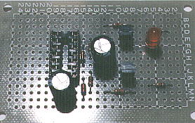
 Mount the resistor R6
 Mount the resistor R6 to 3L and 6L.
 Bend the lead of 3L of R6 to 2L a little.
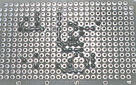
 Bend the lead of 6L of R6 to 5K and bend more to 5J, and cut it at 5J.
 Hold down R6 from the parts side, and adjust the angle of the lead of R6 of 3L side, and put the lead of 6L side lead of R6 to 5J.
 Solder the lead of 6L of R6.
 Cut and leave about 0.5 mm the lead of 3L of R6 so as not to contact with surrounding land.


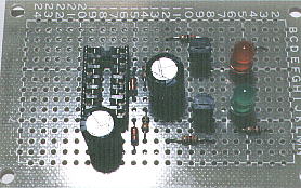
 Mount the Light Emitting Diode D4(green)
 The light emitting diode(LED) has polarity.
The long lead is a anode side( connect to plus voltage ) in the case of a new article. If you don't understand the polarity, see the page 'Light Emitting Diode'.
 Mount D4 to 5J(anode side) and 6J(cathode side) from parts side.
 Mount the LED, providing about 5-mm distance from printed board.
 Solder the lead of D4 and R6 at 5J together.
 Cut the lead of D4 at 5J.
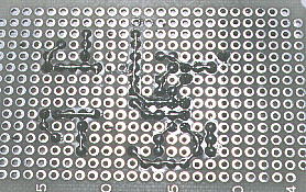
 Bend the lead of D4 of 6J with confirmation of it's hight to 7J, and bend more to 8J and 9J, and cut it at 9J.
 Solder the lead of D4 and TR2 at 9J together.
 Solder at 5K, 6J, 7J and 8L to the turn.


