Procedure of assembly wiring
To each page : 1 , 2 , 3 , 4 , 5 , 6 , 7 , 8 , 9 , 10 , 11 , 12 , 13
Procedure of assembly wiring (1/13)
 The wiring under IC1
This time, tin coated wire of 0.32 mm is used.
The wiring between 16F and 18M does not need to pass under of IC1( the parts side ). This wiring is just to practice.
To avoid the intersection of the connection, the twisted wire covered with soft insulation material can be used instead of tin coated wire. Choose in your taste.
In my case, I make not to use twisted wire as much as possible for easiness of checking.
Don't mistake the position where passes the tin coated wire.(18F and 18K)
This position becomes the starting position of wiring after this. It's better to mark at 18F with red colored pen.
 First, pass the wire from wiring side to parts side at the hole of 18F.
 Pass that wire from parts side to the wiring side at the hole of 18K.
 Put the wire of the 18K to the 18M.
 Hold down the wire of 18K to the printed board, and solder the 18K only.
 Pull the wire of the parts side as it becomes straight from 18F.
Bend the wire of the wiring side toward 16F(right angle to the wire of the wiring side), hold down the wire of 18F to the printed board, and solder the 18F only.
 Cut the wire at 16F.


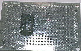
 Mount the IC socket
The hollow where shows the mount direction of IC is attached at IC socket. It has no problem functionally even if it is put in opposite direction. But it's better to put on right direction to avoid careless mistake.
 Mount the IC socket to the parts side. 1st pin is put in accordance with 19E.
 Hold down the socket to the printed board, and solder the 19E(1st pin).
 And solder the 16I(10th pin). With this, the socket is fixed to the printed board.


