Procedure of assembly wiring
To each page : 1 , 2 , 3 , 4 , 5 , 6 , 7 , 8 , 9 , 10 , 11 , 12 , 13
Procedure of assembly wiring (9/13)
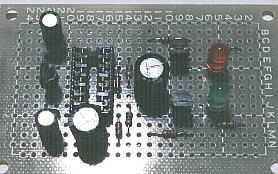
 Mount the capacitor C1
 Mount the capacitor C1 to 21M(minus lead) and 22M(plus lead). Attention the polarity.
 Bend the lead of C1 of 21M to 20M, and 22M to 23M.
Mount the capacitor, providing about 1-mm distance from printed board.
 Solder the lead 22M of C1 and cut it.
 Cut and leave about 0.5 mm the lead of 21M of C1 so as not to contact with surrounding land.
 Mount the capasitor C2
 Mount the capasitor C2 to 21K and 22K.
 Bend the lead of 21K to 20K, and 22k to 23K.
 Solder the lead of C2 at 22K and cut it.
 Cut and leave about 0.5 mm the lead of 21K of C2 so as not to contact with surrounding land.
 Mount the three terminals voltage regulator IC2
 Mount IC2 that flat face(name is printed) toward 23H, and the center lead(ground) to 21H, lead of input to 22I and the lead of output to 22G.
If you don't understand, see 'Component lead of three terminal voltage regulator'.
Mount the three terminal voltage regulator, providing about 5-mm distance from printed board.
 Bend the lead of IC2 of 21H to 20H, 22G to 23G and 22I to 23J.
 Solder the lead of IC2 at 22G and cut it.
 Cut and leave about 0.5 mm the lead of 21H and 21I of IC2 so as not to contact with surrounding land.
 Mount the capasitor C3
 Mount the capasitor C3 to 21E and 22E.
 Bend the lead of 21E to 20E, and 22E to 23E.
 Solder the lead of C3 at 22E and cut it.
 Cut and leave about 0.5 mm the lead of 21E of C3 so as not to contact with surrounding land.
 Mount the capacitor C4
 Mount the capacitor C4 to 21C(minus lead) and 22C(plus lead). Attention the polarity.
 Bend the lead of C4 of 21C to 20C, and 22C to 23C.
Mount the capacitor, providing about 1-mm distance from printed board.
 Solder the lead 22C of C4 and cut it.
 Cut and leave about 0.5 mm the lead of 21C of C4 so as not to contact with surrounding land.


