Procedure of assembly wiring
To each page : 1 , 2 , 3 , 4 , 5 , 6 , 7 , 8 , 9 , 10 , 11 , 12 , 13
Procedure of assembly wiring (4/13)
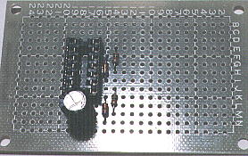
 Mount the capacitor C5
 Mount the capacitor C5 to 17M( positive lead side ) and to 18M( negative lead side ).
At the body of the capacitor the mark that shows negative side lead is printed. Do not mistake absolutely even this.
Mount the capacitor, providing about 1-mm distance from printed board.
 Bend the lead of 17M to 17L, and bend more to 16K. At 16K there is the 8th pin of the IC socket so cut the lead of C5 at 16K so as not to overlap with the lead of IC socket.
 Solder the lead of C5 and IC socket at 16K together.
 Adjusted C5 vertically with printed board.
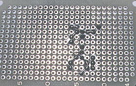
 Cut and leave about 0.5 mm the lead of 18M of C5 that is bended toward 18N so as not to contact with surrounding land.
 Solder the wire that passes under IC1 and the lead of C5 at 18M.
 Solder at 17M, 17L and 18L to the turn.


 Mount the capacitor C6
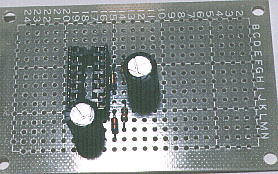
 Mount the capacitor C6 to 12H( positive lead side ) and to 12I( negative lead side ).
Mount the capacitor, providing about 1-mm distance from printed board.
 Bend the lead of 12H to 12G a little.
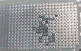
 Bend the lead of 12I to 13J, and bend more to 14J, and cut it at 14J.
 Solder the lead of 12I of C6. This soldering is a little difficult because C6 is tall
 Adjusted C6 vertically with printed board.
 Bend the lead of 12H to 13I, and bend more to 14I and 15I, and cut it at 15I.
 Solder the lead of C6 and the lead of D2 at 15I together.
 Solder at 14J, 13J, 15J, 15H, 14I and 13I to the turn.


