Operation check of RCC with LSD
 Charge of the battery is always done, when AC power supply is normal. Therefore, the measure which prevents an overcharge is necessary. The method used this time is a system called a trickle charge. It is the method of applying for a long time and charging with little current. It is preventing an overcharge in making a charging current little. It may depend on the kind of the battery little but the charging current value of the trickle charging is calculated by the following formula. Charge of the battery is always done, when AC power supply is normal. Therefore, the measure which prevents an overcharge is necessary. The method used this time is a system called a trickle charge. It is the method of applying for a long time and charging with little current. It is preventing an overcharge in making a charging current little. It may depend on the kind of the battery little but the charging current value of the trickle charging is calculated by the following formula.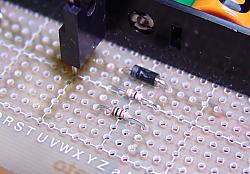 In above-mentioned formula, C is the capacity of the battery. Because the battery to be using this time is 2500mAH, it becomes 0.033 x 2500 = 82.5mA. If it charges by charging current 82.5mA or less, a damage will not be given to a battery even if it has always charged. The resistor of R231 can adjust charging current. In the circuit created this time, it is made about 65mA charging current by the 47-ohm resistor. 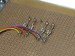 The brightness of the LED depends on the kind of the LED. In the preliminary investigation, the brightness of the large-sized LED to be using for hour and minute display is the darkest. Then, the brightness of other LED is adjusted with reference to the brightness of this large-sized LED. The brightness of the LED depends on the kind of the LED. In the preliminary investigation, the brightness of the large-sized LED to be using for hour and minute display is the darkest. Then, the brightness of other LED is adjusted with reference to the brightness of this large-sized LED.In the specification of the large-sized LED, the maximum electric current is 25 mA. In this circuit, the pulse drive is carried out. It depends on the LED but when the pulse drives, a lot of electric currents can be passed compared with the direct current drive. It is possible to drive in the electric current from twice to 3 times depending on the pulse duration, the period. When not understanding data, not to pour there is safer. Because drive current is a pulse, it cannot measure with the usual circuit tester. I used the oscilloscope, and decided the resistance, measuring the value of drive current. As the result, 32-ohm resistor which connected 100-ohm and 47-ohm in parallel was used, and drive current was set to about 30mA.  It lights up all segments to facilitate an adjustment. Because the circuit this time was pulse drive, I used an actual circuit for the adjustment of the light. I adjusted while connecting resistors temporarily using the cables with the hook chip and seeing the whole light. This work took time and effort most.  I created the test program to adjust brightness. It is the program to make all LED segments light up. To make the LEDs light up by this program, all programs to use by the display control unit must be created beforehand. The program is "LED brightness adjustment program".  Because wiring was classified by color, it could not be wrong, but I made the program to which a display is changed for every second for the check of wiring. Because 2 digits of higher ranks the year are fixation, they do not change. The dot in the lower right of the second display is the display LED of the electric wave reception condition. The actual clock lights up when the reception is normality. The test program blinks every second. Because wiring was classified by color, it could not be wrong, but I made the program to which a display is changed for every second for the check of wiring. Because 2 digits of higher ranks the year are fixation, they do not change. The dot in the lower right of the second display is the display LED of the electric wave reception condition. The actual clock lights up when the reception is normality. The test program blinks every second.A left photograph is animation-ized based on the photograph which photoed the actual display. The display of a day of the week differs from operation of a program. In a program, it changes from Sunday to Saturday and displays from Sunday again after putting out lights for 1 second. In that case, change of a number and change of a day of the week are not in agreement. Therefore, by left animation, the continuity of a day of the week has run out on the way. The program is "LED wiring checking program".  The clock this time is providing the function to sound a time signal for 6:00, 7:00, 8:00, 9:00, 18:00, 19:00, 20:00, 21:00 and the function to sound a chime in 0:00 on January 1st. A time setup of a clock is automatically performed by the electric wave. Therefore, I made the program which checks operation of those functions. The clock this time is providing the function to sound a time signal for 6:00, 7:00, 8:00, 9:00, 18:00, 19:00, 20:00, 21:00 and the function to sound a chime in 0:00 on January 1st. A time setup of a clock is automatically performed by the electric wave. Therefore, I made the program which checks operation of those functions.A chime operation check in case it starts from 23:59 on December 31 and the date changes. The check of the melody skip function from 0:01 on January 1. And the check of a time signal of operation. Time check processing of a time signal is changing Hour to Minute. So, the melody operation with 8 pieces of music can be confirmed at X:06, X:07, X:08, X:09, X:16, X:17, X:18 and X:19. The program is "Time signal operation checking program". The following figure shows the result of having measured the current to each equipment. Digital meter is used for measurement and the greatest indicated value is shown. Because the pulse drive of the control of LED etc. is carried out, actual maximum increases more than these values somewhat. When it changed to a battery drive, the current to CPU changed to 120mA from 18mA. Please look at "LED of a day of the week lights up thinly at the time of a battery drive" of troubleshooting about this phenomenon.  The battery used this time is the capacity of 2500mAH. About 23mA current flows into a CPU unit and a receiver unit. It will continue operating in calculation for 2500/23 = 108.7 hours. However, because the voltage will fall if the residual quantity of a battery decreases, it cannot operate until it uses all up. If residual quantity of a battery decreases, voltage will descend rapidly. A certain amount of voltage is maintained till then. I made the battery full charge and actually operated it. Continuation operation was carried out between four days of circles for about 100 hours. This is operating time until LCD disappears. The clock itself was operating a little longer. It is as calculation mostly. |