Processing explanation of Decorative light Controller
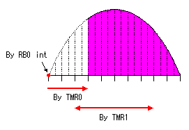
 Three kinds of interruptions are used on this software. The following explanation is in case of 50 Hz. Three kinds of interruptions are used on this software. The following explanation is in case of 50 Hz.
In case of TMR0 and TMR1, TRIAC1 to 5 are conrtolled sequentially. ;*************** RB0 interruption process ***************
- Initialization of TMR0 - Initialization (0) of the index (tmr0_index) which manages a control position for every interruption of TMR0 - Initialization (OFF) of the data (porta_work) for holding the ON/OFF state of TRIAC - Initialization (OFF) of PORTA which controls ON/OFF of TRIAC ;************** TMR0 interruption process ***************
By this interruption, the timing which makes a TRIAC ON is controlled. The timing which makes a TRIAC ON is indicated by TRIAC control memory (TRIACx). The index (tmr0_index) of TMR0 is increased in 1 every time the interruption of TMR0 occurs and is made ON condition in the TRIAC when becoming the same as the value of the TRIAC control memory. Therefore, if the value of TRIAC control memory is small, the timing turned ON will become early and a lamp will come on brightly. If a value is large, timing will become late and a lamp will become dark. ;***** Timer1 interruption process (50ms interval) ******
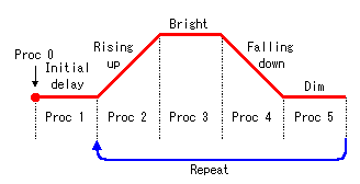
In the pattern switch reading processing, it specifies a switch by 3 bits of higher ranks (RB7-5) of PORTB. After that the reading of PORTB is done. The timing for 750 microseconds is prepared after carrying out switch specification until it reads PORTB. The condition of the switch is stored in RB4-1. So, it is 1 bit shifted to the right and it sets to 4 bits of lower ranks once more. In the read data, 0 and 1 are reversed. So, it is reversed using xorwf instruction. 4 bits of lower ranks are picked up and are stored in portb_work. The condition of the switch is stored in swx_mode. However, it isn't changing if the contents of portb_work and swx_mode are the same. In the case, storage processing isn't done. When the contents of portb_work and swx_mode were different, the setting of a switch was changed. In this case, read data is stored in swx_mode. Moreover, the process number (tx_proc) to use in the control timing for TRIAC is cleared. Pattern data is initialized by this. All switch readings were performed by one processing in the early design. However, since control time was short, a decoder did not operate normally. Then, I changed into the processing which reads the state of one switch by one processing. Therefore, reading is done a maximum of 250 milliseconds later after change of the position of the switch. There is no problem. Control timing process for TRIAC is started up every twice of interruption of TMR1. So, the interval is 100 milliseconds. In this processing, the data which controls the light of the lamp is set to TRIAC control memory (TRIACx). TRIAC is controlled by TMR0 interruption processing based on the set-up data. For the details of this processing, look at the following pattern processing. ;*********** Pattern process (100ms interval) ***********  Pattern processing is started every 100 milliseconds by the interruption processing of TMR1. In this processing, the control timing of the TRIAC is managed in five processes.
Also, at the ending processing, it sets initial delay data for process 1 to the processing counter.
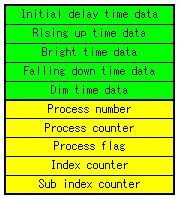
In end processing of process 1, data-preparation processing for process 2 is performed. The processing of rising up which is done in process 2 is complicated a little. The contents of processing change with the value to set up. Since brightness control is ten steps, processing changes by setting data. 20 or more or else less than 20. When a setup is 20 or more, the same TRIAC control value must be repeated. For example, when setting data is 40, each 20 stages are repeated twice. The number to repeat is set to the index counter. When the setting data is less than 20, some stages should be skiped. For example, when the setting data is 5, the stage is controlled every four. Like 4th stage -> 8th stage -> 12th stage -> 16th stage -> 20th stage. The number of the stages skipped is set to the sub index counter. A processing flag area is used for the indication of 20 or more or else less than 20. In case of 20 or more, the flag is set to 1 and in case of less than 20, the flag is set to 0. In case that the value of TRIAC control memory (TRIACx) is 20, it is dim. And in case of the value is 0, it is bright. So. In the processing which makes bright from dim, a decrease with the value of TRIAC control memory (TRIACx) is done.
At the ending processing, bright time data for process 3 is set to the processing counter.
At the ending processing, a flag, an index, a sub index are set like the ending processing of process 1. However, the setting contents are different. It's the processing to increase from 0.
At the ending processing, dim time data for process 5 is set to the processing counter.
At the end processing, the same processing as end processing of a process 1 is performed. Utilizing end processing of a process 1 is also considered. However, I made the source code different from a process 1, in order to avoid the complicatedness of processing. The following process is set as 2. Therefore, it repeats like Process 2 -> process 3 -> process 4 -> process 5 -> process 2 -> ... after this.
;*** Frequency of AC power. 50Hz or 60Hz
In case of 50 Hz, the period of the half cycle is 10 milliseconds. It makes the time of TMR0 1 millisecond and interruption with 10 times is generated in the half cycle. In case of 60 Hz, the period of the half cycle is 8.33 milliseconds. It makes the time of TMR0 0.833 milliseconds and interruption with 10 times is generated in the half cycle. ;*** Control Pattern. Available 0 to 255 (unit=100ms)
The contents are the same as the yellowish green contents shown with the Structure of execution management memory. The unit of the data is 100 milliseconds. It is possible to set in a maximum of 255. As note point, in case of less than 20, make 0, 1, 2, 4, 5 or 10. Also, in case of equal to or more than 20, make 20 multiples. This is because the control number of stages of TRIAC is 20 steps. It's not effective even if you set up values other than the above. At the value except the above, the error doesn't occur. Since it is control of a lamp, it is not effective even if it carries out strict control. The example of a pattern 0 is shown below.
|
