Processing explanation
of Count-down timer
;********************************************************
;
;             The Count-down timer processing
;
;                                 Author : Seiichi Inoue
;********************************************************
        list            p=pic16f84a
        include         p16f84a.inc
The standard label definition of PIC16F84A is read by the INCLUDE directive. As for the change of the standard label definition of PIC16F84A, refer to "Processing explanation of signboard". Or you can use ERRORLEVEL directive to suppress the Warning messages.
__config _hs_osc & _wdt_off & _pwrte_on & _cp_off
As for the contents of operand, refer to "Processing explanation of signboard".
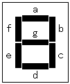
;**************** Label Definition ******************** The definition of the label constant to use by the processing is done. The standard label of PIC16F84A is read in INCLUDE directive. The pattern definition of the 7 segment LED is specified by the EQU, too. A pattern is shown below.
;**************  Debugging mode setting  ****************
;For debugging mode, ";" of next line should be removed.
;#define  _debug
This time, the initial value of the counter value, the set value of the timer, the condition of the stop switch are set for the debugging. However, this time, I was made to be able to change the part to assemble by the definition of the '_debug' label. For the details, refer to "Debugging of Count-down timer". ;**************** Program Start *********************** Instruction is executed from Zero addresses of the program memory when making the power ON of the PIC. When there is interruption processing, processing is begun from the addresse 4. It makes each processing jump with the GOTO instruction. ;**************** Initial Process ********************* The following processings are done as the initialization processing after the turning on.
;************* Timer stand-by Process ***************** In the condition that the count-down of the timer hasn't started, the following processing is repeatedly executed. ;************** Timer start Process *******************
To decide the interruption time of the timer, there is a following element.
Processing since then is repeatedly executed until there is a time-out.
;************** LED Control Subroutine **************** The contents of the counter are output to the LED in order of the 10th of the minute, the 1st of the minute, the 10th of the second, the 1st of the second. ;******* Change BCD to 7segment data Subroutine ******* It changes from the data of the binary-coded decimal code into the data in 7 segments and outputs to port B. ;************* 1msec Timer Subroutine *****************
When using at the input mode like the BCD switchs, the start switch, it executes a 1-millisecond wait before reading the condition of the device after specifying a device. When using at the output mode like the 7 segment LEDs, it executes the processing of the following device after waiting 1 millisecond after presenting the lighting-up information of the LED. It is difficult to know a necessity in the waiting time by the simulation of MLPAB. I understood it by the operation of the actual circuit. It is necessary to consider in the operating time of the hardware, too. This subroutine is diverting the processing which was made in "LED flasher". ;************ Begin Interruption Process ************** It does the saving of W register and the saving of STATUS register and it confirms a timer interrupt. The point which should be careful here is in the bank condition. When the interruption occurs immediately after changing a bank to 1 in interruped processing, it sets SFR which was mistaken by the interruption processing. So, it is executed in the processing which changes a bank to 0 after the saving of STATUS register is ended. ;************ END of Interruption Process ************** It returns STATUS register and W register and it ends the interruption processing with the interruption ending instruction (RETFIE). With this, it becomes the interruption possible condition. SWAPF instruction is used for the processing to return W register so as not for the contents of the STATUS register to change. ;*********** Time-out interruption Process ************ This processing is executed when the timer TMR0 of the hardware does in the time-out. To have count-down processing every second, it is short only at the hardware timer. (A maximum of 26 milliseconds in case of the 10-MHz clock) So, it counts the interruption of the hard timer by the software and it is making execute count-down processing every second. I decide the set value of the hard timer and the count value of the software to minimize the error of the count-down. ;************* Timer count-down Process *************** Processing is executed every second. It is checking first, do subtract the 1st counter in the second and whether or not it becomes 0. In case of 0, because there is possibility of the time-out situation, it is doing the checking whether or not all counters are 0. To judge 0 of the counter, it reads counter content by the movf instruction and it is checking the Z bit of the STATUS register. The Z bit is '1' means the contents of the counter are 0. When either counter is not 0, because it is not in the time-out condition, count-down processing is executed. In the count-down processing, it checks the contents of each counter and in case of 0, a maximum is set. The maximum of the 10th of the second is 5 and as for the other digit, 9 is a maximum. When the contents of the counter are not 0, it subtracts one. In the interruption processing, only time-out checking and count-down processing are executed. The time-out processing(Timer stop and Relay OFF) and the LED display processing are executed by the timer start processing. ;********************************************************
; END of signboard control processing
;********************************************************
endAt the end of coding, END directive is used. |
|||||||||||||||||||||||||||||||||||||||||||||||||||||||||||||||||||||||||||||||||||||||||||||||||||||||||||||||||||||||||||||||||||||||||||||||||||||||||||||||||||||||||||||
