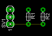
Schematic making technique (3)
|
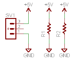
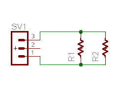
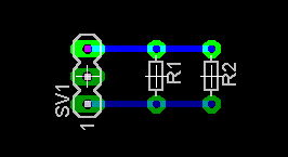
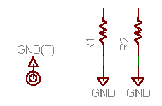
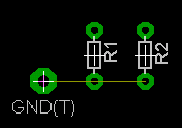
On the schematic, power and ground are frequently used. The powers or the grounds which are put on the schematic can be connected with line directly. But the schematic becomes complicated and becomes difficult to see. In the such case, when using a power or ground symbol, the schematic becomes easy to see. Of course, the power and ground are normally connected on the board which is created from the schematic which was drawn with those symbols.
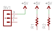
The power symbol which suited each voltage must be used like +5V, +12V so on. When the wiring should be separated at the same voltage, the different symbol must be used like +5V(A), +5V(B) so on. A symbol attribute is decided by the terminal name of the symbol data. The necessary power and ground symbols should be created before drawing a schematic. When using a connector for the input terminal of the power, it is possible to wire if putting a power symbol to the connector pin. Net
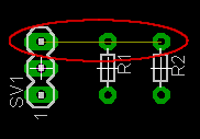
When using a symbol, even if it wires with Wire command, it isn't wired on the board.
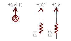
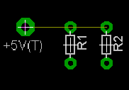
If making a power symbol with the terminal in the library, the independent power input terminal can be drawn.
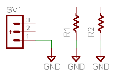
The ground symbol substitutes for the wiring among the parts terminals on the schematic like the power symbol.
Because more electric currents flow through the power line and the ground line than the signal line, it is necessary to be drawn with the wide pattern. There is a way of using Net Class to specify the thickness (the width) of the pattern. Here, I let's explain the attention point when using Net Class. The pattern can be manually drawn with the board even if it doesn't use Net Class. In the case, the wiring width can be specified by the Route icon. 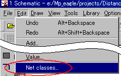 First of all, it sets Net Class. This time, I set Net Class for the power and the ground. I think that it's easy to find out the one to have made the same as the terminal name of the power symbol and the ground symbol as Name. The name doesn't influence pattern creating even if it isn't the same. 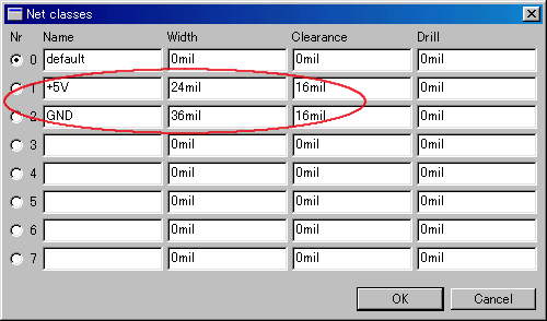 As for the example, I use the circuit which has three resistors wired with the power and the ground symbol. 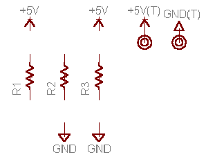  It wires using Net. At this time, it specifies an appropriate class by Net Class. When this specifying isn't done, the pattern with the width to hope for isn't made. It draws wiring while specifying a class on the schematic.
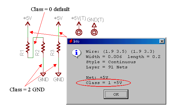  It pushes the Board button and it creates a board. The figure below is in the condition to have arranged the parts on the board area. 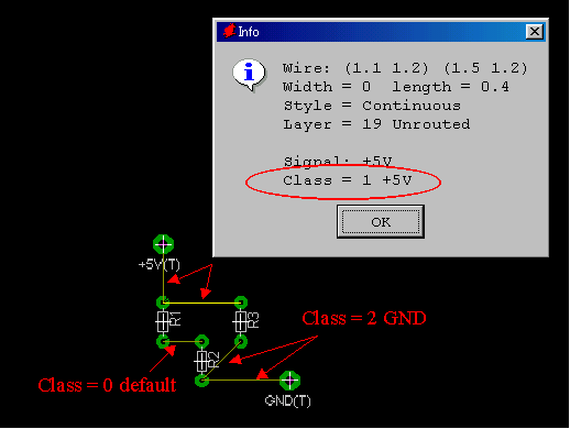  It does automatic wiring by the Aout button. This time, I set "1 Top" of Preferred Directions in "N/A" and drawing a pattern only at Bottom(wiring side). 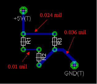 You can find out the pattern drawn with the width specified by Net Class. |
||||||||||||||||||||||||
