 Power and Ground symbol making Power and Ground symbol making
The techniques which are introduced here are the wiring technique which connect a lot of point on the schematic like power or ground without direct wiring. The power and the ground of the parts which are put a lot of place on a schematic can be done with the directly wiring, but the schematic becomes complicated. When you make parts for power and ground symbol, the connection of each terminal wiith the wire isn't necessary.
 Power symbol ( Without terminal ) Power symbol ( Without terminal )
 Symbol data making Symbol data making

It clicks Symbol icon and creates symbol data newly. This time, I put a name "+5V".
To create symbol data, refer to "New parts making", too.
 Pin setting Pin setting

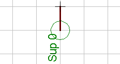
First, it pushes Pin icon and draws a terminal.
 I set Pin as follows. Direction of the pin should be set to "Sup".
| Orientation |  | R90 |
| Function |
| None |
| Length |
| Short |
| Visible |
| Off |
| Direction |
| Sup (Should be) |
| Swaplevel |
| 0 |
|  |
 Drawing of a symbol Drawing of a symbol
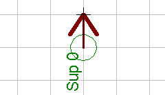
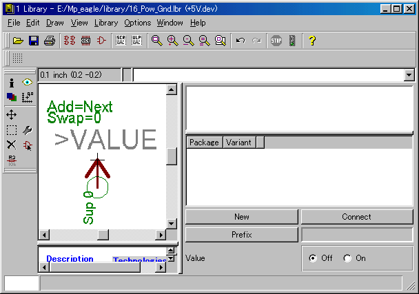
 It pushes Wire icon and draws a symbol for the schematic. I did to the symbol of the arrow. It pushes Wire icon and draws a symbol for the schematic. I did to the symbol of the arrow.
For the drawing method of the symbol, refer to "Drawing of a symbol".
To draw a diagonal line, it adjusts a grid interval.
|  |
 Pin name setting Pin name setting

It pushes Name icon, and clicks a setting pin and sets the name of the terminal.
This name is important. This terminal name becomes the common name when doing a connection.
When drawing more than one power symbol of +5V on the schematic, the connection on the board is done based on this name. So, it is necessary to be an unique name with the schematic. Wrong wiring is done when the same name is used for the terminal of the other symbol. | 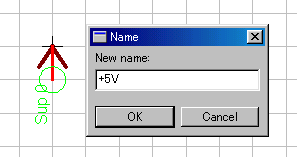 |
 Value designating Value designating
 It sets a symbol value. It sets a symbol value.
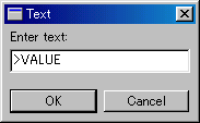
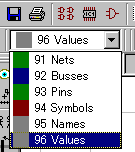
The value must be set to the 96th layer.
 |
->
 |  |
->
 | 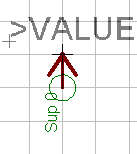 |
| It types with ">VALUE" to the text box and it pushes the OK button. ">VALUE" which moves with the mouse pointer is indicated on the window. |
|
The layer must be changed.
Select 96 Values and change to the layer of the value. |
| After above setting, it puts a text near the symbol. |
The creating of symbol data ended above.
 Device data making Device data making
It creates the device data to put a part on the schematic. In case of the power part(Without terminal) which is created this time, the package data which is used with the board is unnecessary.

It pushes Device icon and creates device data. | 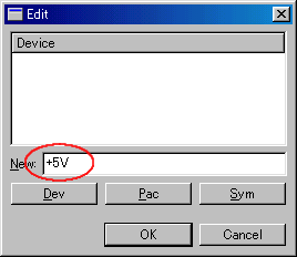 |
 Addition of the symbol data Addition of the symbol data

It pushes Add icon and adds the symbol data of +5V.
 Symbol name setting Symbol name setting

It pushes Name icon and clicks a terminal and sets a name. Even if it doesn't do this setting, there is no influence for the operation. | 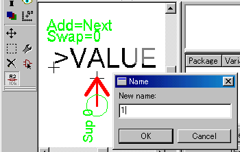 |
 Device description setting Device description setting

The description of the device can be set by Description.
It clicks Description in the lower left window.
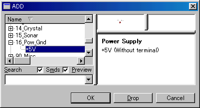
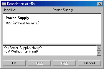 This description is displayed in the Description column when adding a part with the schematic.
|


 It sets a symbol value.


 It pushes Wire icon and draws a symbol for the schematic. I did to the symbol of the arrow.


