Frequency induction switch
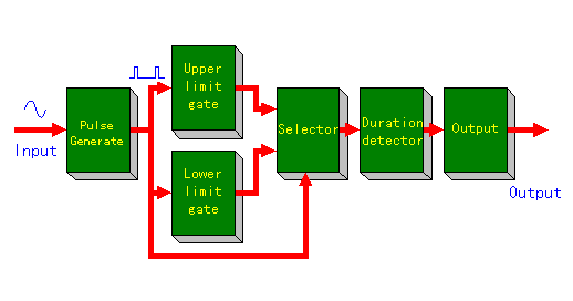
 Block diagram of the top is a clockable image map. You can jump to each page of the explanation when you click each block. |
|
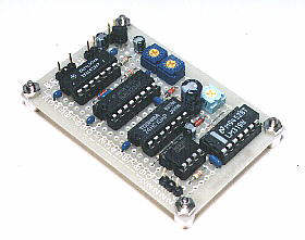
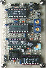
This circuit is the circuit which makes the output the high level condition when the signal of the specific frequency which is is inputted. I made this circuit in the purpose to reset the clock( adjust the minute correctly ), detecting the time signal of the radio. I think that it is possible to apply with the variety as well as it, too.
The band pass filter : The filter circuit which only the specific frequency makes pass The circuit which I am introducing in this page is designing to be able to be set in the range that the input frequency is about 780 Hz-1090 Hz. Because the frequency of the time signal in the broadcasting station in Japan is 880 Hz, this is made to be able to be adjusted near it. The output is high level (+5V) of the TTL. To have shown by the block diagram above, first, it changes the input signal into the pulse signal of the same frequency. The signal is output from selector only when the frequency of the pulse signal is between the upper limit gate and the lower limit gate. It makes detect only when the signal continues to prevent from the malfunction. In the output block, it makes the output the high level condition based on the signal which was detected in the duration detector block. It continues the high level of the about 500 milliseconds. |
 |
|
 |  |