Parts explanation of Stepper Motor controller
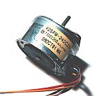 This is a 2-phase unipolar PM type stepper motor with 48-poles.
 The control of the stepper motor is done by this PIC. To have explained in the operation principle,  This is used to make the stable voltage of +5V. A 100-mA type is used.  This is a Darlington connection-type transistor.  At first, I used 2SD1590 ( 8A type ) as the transistor for the drive. However, in case of the motor which was used this time, the coil current was about 250 mA. So, I changed into the small type transistor. The maximum collector current of 2SD1209K is 1A and "hfe" is more than 4000.  This is the transistor to control the speed of the motor. 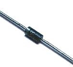 This is the diode to protect a transistor from the back electromotive force which occurs with the coil of the stepper motor. It depends on the kind of the stepper motor but it is to be OK if it is possible to pass a hundreds-of-mA electric current. 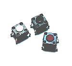 This is a switch for the clockwise rotating, the counterclockwise rotating or making a motor stop. 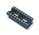 This is the socket to mount PIC16F84A. 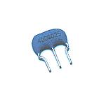 This is a 4 MHz resonator. 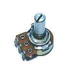 B type is used. 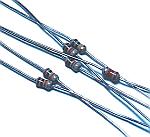 It is to be OK at 1/8 W.  This is the series resistor to be using for start/stop switch pull up.  This capacitor is used to bypass the high frequency noise of the input and output of the power supply. 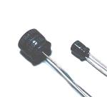 This capacitor is used as the ripple filter capacitor of the power circuit. 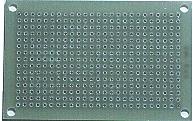 This is an universal printed board with 15 x 25 halls.  This terminal is used to connect a power supply wire and the variable resistor for the speed control.  A 6-pin connector is used to connect a stepper motor. The motor used this time, 5-pin connector is OK. Because the power of the X coil and the Y coil is connected inside the motor. However, a power line is divided by the kind of the motor. So, 6-pin are used for two power lines to be able to be connected.  This is used as the leg of the printed board. |