Circuit explanation of Stepper Motor controller
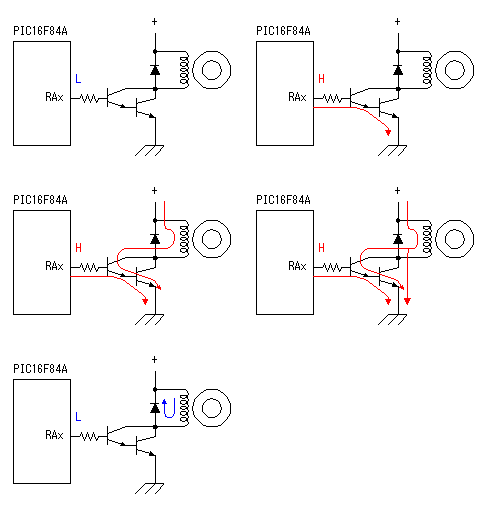 This is the circuit which drives the coil of stepper motor. There are circuits which drive Darlington connection-type transistor is used for the drive of the coil. As for the Darlington connection, 2 stages of transistors are connected inside in series. The "hfe" of this transistor is the multiplication of the "hfe" of each transistor inside. In case of 2SD1209K which was used this time, the hfe is over 4000. Because the ratio of the input electric current and the output current is big, the rising edge and the falling edge of the control signal can be made sharp. The diode to be putting between the collector and the power is for the protection of the transistor. When the transistor becomes OFF from ON, the coil of the motor tries to continue to pass an electric current and generates high voltage. An electric current by this voltage is applied to the diode and the high voltage which applies over the transistor is prevented. 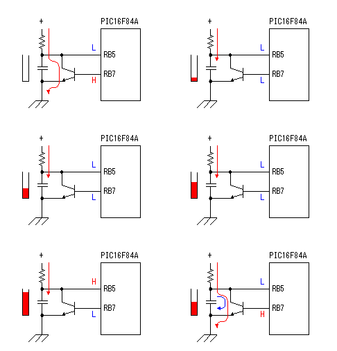 This is the circuit which controls the rotational speed of the motor. This is the circuit which controls the rotational speed of the motor.TR1 becomes ON condition when RB7 becomes H level. In this condition, the electric charge of capacitor C1 flows through the transistor and the voltage of the both edges of the capacitor becomes 0 V almost. When RB7 becomes an L level, the transistor becomes OFF condition. In this condition, the electric current flows through VR1 and R4 into capacitor C1 and the charging to the capacitor begins. The voltage of the both edges of the capacitor becomes high gradually as charging is done. As for the change of this voltage, refer to "Integration circuit". The voltage of the capacitor is detected by RB5. The software of PIC interrupts the control of the motor until it checks RB5 after making RB7 an L level and RB5 becomes H level. When making the value of VR1 small, the charging time of the capacitor is short and the control of the motor becomes quick. The control of the motor becomes slow when making VR1 big. The speed control range can be changed by changing the value of the capacitor. 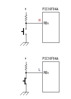 This is the circuit for the clockwise rotating, the counterclockwise rotating or stopping a motor. The baton switch of the non lock is used. Pull-up resistor is used for the port to become H level when the switch is OFF. The RB port of PIC16F84A has an internal pull up feature. However, because RB5 is used for the voltage detection of the capacitor at the circuit this time, an internal pull up feature isn't used. If using RA port for the voltage detection of the capacitor, the RB internal pull up feature can be used. The circuit this time put an external pull-up resistor in the relation of the pattern. This is the circuit for the clockwise rotating, the counterclockwise rotating or stopping a motor. The baton switch of the non lock is used. Pull-up resistor is used for the port to become H level when the switch is OFF. The RB port of PIC16F84A has an internal pull up feature. However, because RB5 is used for the voltage detection of the capacitor at the circuit this time, an internal pull up feature isn't used. If using RA port for the voltage detection of the capacitor, the RB internal pull up feature can be used. The circuit this time put an external pull-up resistor in the relation of the pattern.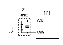 4-MHz resonator is used because the circuit this time doesn't need high-speed operation. 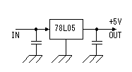 The purpose of this circuit is to keep power supply voltage to PIC to 5V when the power of the stepper motor is more than 5V. Because the operating voltage of the stepper motor to be using this time is about 5V, the power supply voltage is +5V. In this case, the voltage which is applied to PIC becomes less than 5V because of the voltage drop (about 1V) of the regulator. In case of PIC16F84A, the operation is possible even if the power falls to about 3V because the operating voltage range is from 2V to 5.5V. It is enough in the 100-mA type. |