Circuit explanation
for the ultrasonic alarm (2)
The circuit this time is the same as the circuit for Ultrasonic Alarm (1) except Alarm detector. As for the circuit explanation except Alarm detector, please refer to the circuit explanation for Ultrasonic Alarm (1) which is linked from the following items.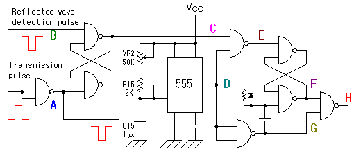 The alarm detector circuit is different from Ultrasonic Alarm (1). In Ultrasonic Alarm (1), an alarm output is presented when there is a reflected wave from the object in the setup time. At the circuit this time, an alarm is output when no reflected wave from the object is detected in the setup time oppositely. The existence of the reflected wave in the setup time is detected like Ultrasonic Alarm (1) to do this operation. As for the time setting for 555 timer and so on, please refer to Alarm detector of Ultrasonic Alarm (1). The alarm detector circuit is different from Ultrasonic Alarm (1). In Ultrasonic Alarm (1), an alarm output is presented when there is a reflected wave from the object in the setup time. At the circuit this time, an alarm is output when no reflected wave from the object is detected in the setup time oppositely. The existence of the reflected wave in the setup time is detected like Ultrasonic Alarm (1) to do this operation. As for the time setting for 555 timer and so on, please refer to Alarm detector of Ultrasonic Alarm (1).I will explain the operation of Alarm detector circuit which is used this time below. 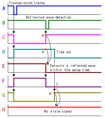 The initialization of the circuit is done with transmission timing pulse (A). C to "L", D and F to "H", G to "L" by which D goes to "H". When a reflected wave is detected within the setup time of 555 timer, C goes to "H". With this, the E shifts to "L". When the E goes "L", F shifts "L" and it is held until the next initialization. G shifts to "H" when D goes "L" with the time-out of 555 timer. However, because F is "L", the alarm output H is held on "H" and an alarm signal isn't output. 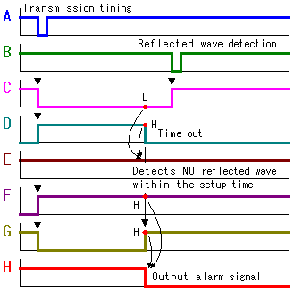 The initialization of the circuit is done with transmission timing pulse (A). C to "L", D and F to "H", G to "L" by which D goes to "H". When a reflected wave isn't detected within the setup time of 555 timer, the change of the E doesn't occur. It is held on "H". When D goes to "L" by the time-out of 555 timer, G shifts to "H". Because F is held on "H", H shifts to "L" and an alarm signal is output. Even if a reflected wave is detected behind the time-out of 555 timer, because D is held on "L" already, the change of the condition of E doesn't occur. It is held on "H". So, the alarm output is kept. 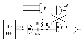 Alarm detecting circuit is composed of SR-FF (The set and reset type flip-flop circuit) and 555 timer. The reset of SR-FF for alarm detecting which is composed of IC8 must be reset in the timing of the rising edge of the timer. The set and the reset of SR-FF are done by the L level. Therefore, the signal which reversed the output of the timer is used for the reset signal. Also, SR-FF must be reset only when timer operation is started. So, the pulse signal which is made with CR-type differentiation circuit is used. D6 is put for the input protection of N2. When the timer does in the time-out, the output of N1 shifts to the H level from the L level. At this time, an electric charge with power supply voltage is already stored up in C25. When there is not D6, 2 times of voltage of the power are applied to the input of N2. The forward voltage of the diode is less than 1V. So, the voltage to apply input of N2 becomes the forward voltage of diode + power supply voltage. Alarm detecting circuit is composed of SR-FF (The set and reset type flip-flop circuit) and 555 timer. The reset of SR-FF for alarm detecting which is composed of IC8 must be reset in the timing of the rising edge of the timer. The set and the reset of SR-FF are done by the L level. Therefore, the signal which reversed the output of the timer is used for the reset signal. Also, SR-FF must be reset only when timer operation is started. So, the pulse signal which is made with CR-type differentiation circuit is used. D6 is put for the input protection of N2. When the timer does in the time-out, the output of N1 shifts to the H level from the L level. At this time, an electric charge with power supply voltage is already stored up in C25. When there is not D6, 2 times of voltage of the power are applied to the input of N2. The forward voltage of the diode is less than 1V. So, the voltage to apply input of N2 becomes the forward voltage of diode + power supply voltage.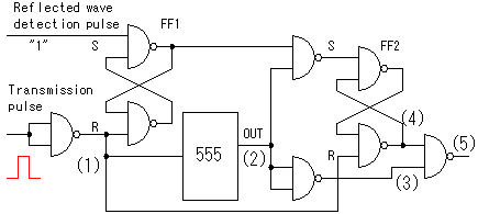 In the left figure, a transmission pulse is used for the initialization of SR-FF(FF2) for the alarm detection. In case of this circuit, normally initialization operation isn't done. I will explain the reason using time chart why normally initialization operation isn't done. 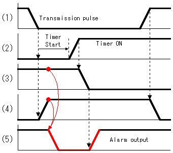 In the figure, the part of the transmission pulse is expanded. To be drawing rising edge and falling edge by the slanting line shows the transition time. The problem is the time that the output of the timer becomes ON. It takes time the output of the timer becomes ON even if it starts 555 timers by the transmission pulse. FF2 is immediately reset by the transmission pulse and signal (4) becomes H level because of the high-speed operation of the NAND circuit. As a result, alarm signal (5) occurs in short time to have drawn by the red line. This signal is several microseconds. However, it is enough time to make do the operation of the alarm hold timer.(Refer to the schematic) Therefore, the alarm hold timer has always operated At the circuit this time, the initialization of FF2 is done by the falling edge signal (3) of 555 timer. So, it doesn't let out an alarm signal by the initialization operation. |