[Menu]>[Electronic circuit engineering introduction]>[Assembly process]
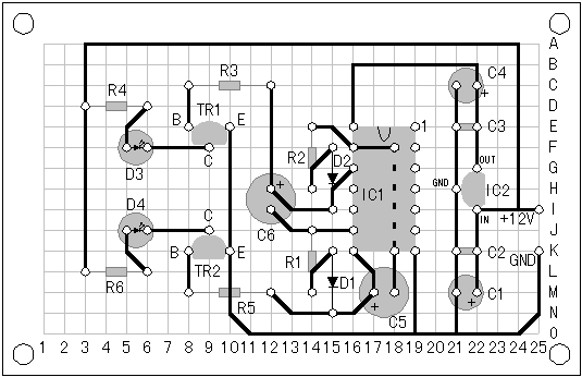
Printed circuit drawing
of a-stable multivibrator


This drawing shows wiring side. So, you are watching from the bottom of the part. You need to do so as not to mistake the position of the component lead of the parts such as ICs, transistors etc. Usually the pin arrangement drawing of IC is entered with TopView. then the pin arrangement becomes opposite on this drawing.
Although I understood after assembled this circuit, the mounting position of IC1 should have been made 1 hole upper.
I have thought that the position of IC1 at the center of the printed board is good balance. But C5 is too big, then IC1 and C5 have contacted. There is not a problem even if it contacts.
The above wiring drawing is being used in the procedure of the assembly wiring in this time. I think that it is good to change the mounting position of IC1 when you make it.There is not a problem also in the wiring drawing that showed it upward.
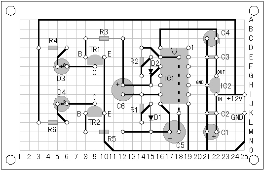
For reference, the printed circuit drawing where changed the mounting position of IC1( Modification version ) is shown below.
 Printed circuit drawing ( Modification version )


