Parts explanation of RCC with LSD
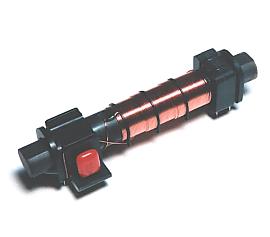 This is the bar antenna to receive the radio wave of 40KHz. |
 This is the exclusive use IC to take out the time information which is carried in the radio wave of 40KHz. At the data sheet, a radio clock system in some countries is introduced. |
|||||||||||||||||||||||||||||||||||||||||||||||||||||||||||||||||||||||||||||||||||||||
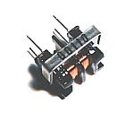
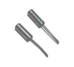 These crystal oscillators are used to receive the radio wave of 40KHz, being connected with receiver IC(U4226B). |
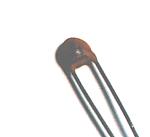
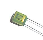 In order to carry out operational stability of the receiver circuit, the capacitor of high capacity accuracy is required. |
|||||||||||||||||||||||||||||||||||||||||||||||||||||||||||||||||||||||||||||||||||||||
 This is also used for a receiver circuit. |
 The kit is designed so that a receiver circuit and a display control circuit can be installed in a different place. They are connected by a cable. Therefore, the photo coupler is used for the signal drive. |
|||||||||||||||||||||||||||||||||||||||||||||||||||||||||||||||||||||||||||||||||||||||
 This transistor is used for the LED drive, etc. Data sheet for 2SC1213 |
 This is a coil for removing the noise generated when a receiver unit and a CPU unit are connected by a long cable. |
|||||||||||||||||||||||||||||||||||||||||||||||||||||||||||||||||||||||||||||||||||||||
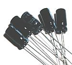 These capacitors are used in order to stabilize the supply voltage of a circuit. |
 This is a regulator for making the power supply (+5V) of a receiver circuit. |
|||||||||||||||||||||||||||||||||||||||||||||||||||||||||||||||||||||||||||||||||||||||
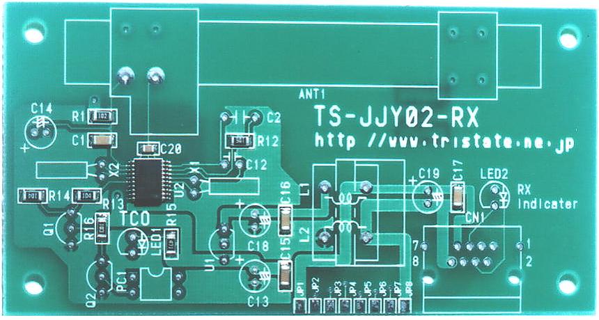 The printed board of the receiver unit is using the one of the kit. IC for the receiver, chip resistors and chip capacitors are already mounted on the board. |
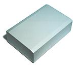 As the case of receiver PR-140G made by TAKACHI is used. It's the case with a width of 140mm, a height of 45mm, and a depth of 90mm. |
|||||||||||||||||||||||||||||||||||||||||||||||||||||||||||||||||||||||||||||||||||||||
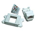 RJ-45 connector is used for the cable connector of a receiver and a display processor. |
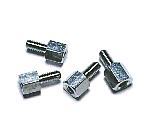 This metal stud is used to fix a printed circuit board on the case. |
|||||||||||||||||||||||||||||||||||||||||||||||||||||||||||||||||||||||||||||||||||||||
 In the kit of TriState, PIC16F873 is used and the port to control a display unit outside isn't enough. So, in this circuit, 877 with many ports is used by 873 higher rank models. |
||||||||||||||||||||||||||||||||||||||||||||||||||||||||||||||||||||||||||||||||||||||||
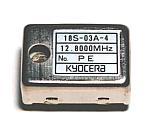 This is a high precision crystal oscillator for displaying exact time, even when a radio wave stops. Oscillation frequency is 12.8MHz. |
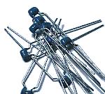
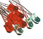 These LEDs are used in order to check the operating state of a circuit. |
|||||||||||||||||||||||||||||||||||||||||||||||||||||||||||||||||||||||||||||||||||||||
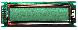 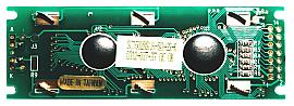 This is a liquid-crystal-display panel (LCD) for displaying time. This is a liquid crystal display made by SUNLIKE Co. in Taiwan. The display of two lines can be performed by 16 characters per line. |
||||||||||||||||||||||||||||||||||||||||||||||||||||||||||||||||||||||||||||||||||||||||
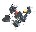 This clock has a function to control the outside circuit when becoming a set time. These switches are used in order to set up the time. This clock has a function to control the outside circuit when becoming a set time. These switches are used in order to set up the time. |
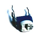 This is a variable resistor for adjusting the display contrast of LCD. |
|||||||||||||||||||||||||||||||||||||||||||||||||||||||||||||||||||||||||||||||||||||||
 This is melody IC. 8 pieces of music are memorized in this IC.
|
||||||||||||||||||||||||||||||||||||||||||||||||||||||||||||||||||||||||||||||||||||||||
 This is the small amplifier which is possible to let out an about 500-mW output power. It is convenient because it doesn't need a related part. This is used for the amplification of the time signal( Electronic music ). Datasheet for LM386 |
||||||||||||||||||||||||||||||||||||||||||||||||||||||||||||||||||||||||||||||||||||||||
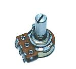 This is the variable resistor to adjust the volume of the time signal. |
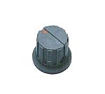 This is the knob which is used for the volume. |
|||||||||||||||||||||||||||||||||||||||||||||||||||||||||||||||||||||||||||||||||||||||
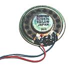 This is the small speaker to sound the music of the time signal. |
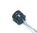 This is the capacitor used for coupling of a time signal circuit. |
|||||||||||||||||||||||||||||||||||||||||||||||||||||||||||||||||||||||||||||||||||||||
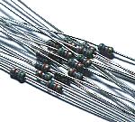 This is the small resistor of 1/6W. |
 These capacitors are used as a high frequency bypass of a power supply system. These capacitors are used as a high frequency bypass of a power supply system. |
|||||||||||||||||||||||||||||||||||||||||||||||||||||||||||||||||||||||||||||||||||||||
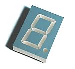
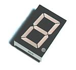
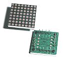
 In order to make all the 7 segments LED turn on simultaneously, a big power supply is required. With this equipment, the lighting position of LED is changed at high speed, and the power of it is saved. The number of the 7 segments LED to control is 14. In order to control such LEDs, PIC16F628 is used. The dot matrix LED of 8x8 is used for the display of a day of the week. In order to control this LED, another PIC16F628 is used. |
||||||||||||||||||||||||||||||||||||||||||||||||||||||||||||||||||||||||||||||||||||||||
 In order to control the display position of a dot matrix LED, the 8-bit decoder is used. Only one of 8 bits is set to L level with a 3-bit control signal. |
 |
|||||||||||||||||||||||||||||||||||||||||||||||||||||||||||||||||||||||||||||||||||||||
 This transistor is used for the display unit. Data sheet of 2SC1815 |
 This transistor is used for the display unit. Data sheet of 2SA1015 |
|||||||||||||||||||||||||||||||||||||||||||||||||||||||||||||||||||||||||||||||||||||||
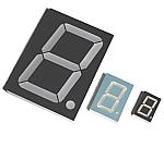  120mm(H), 90mm(W), 15mm(D) |
  50mm(H), 37mm(W), 13mm(D) |
|||||||||||||||||||||||||||||||||||||||||||||||||||||||||||||||||||||||||||||||||||||||
  33mm(H), 22mm(W), 9mm(D) |
  33mm(H), 33mm(W), 4mm(D) |
|||||||||||||||||||||||||||||||||||||||||||||||||||||||||||||||||||||||||||||||||||||||
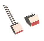 Square LED is used for the pause of Hour and Minute. Square LED is used for the pause of Hour and Minute.Long and slender LED is used for the pause of Year, Month and Day. |
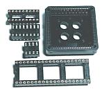 It sometimes removes PIC and CPLD to rewrite a program so an IC socket is used. It sometimes removes PIC and CPLD to rewrite a program so an IC socket is used. |
|||||||||||||||||||||||||||||||||||||||||||||||||||||||||||||||||||||||||||||||||||||||
 This is a regulator for making the power supply (+5V) of a CPU unit. The regulator for 100mA was used at the beginning.However, because about 100mA current flowed at the time of battery drive, it was changed into 1A type for safety. Data sheet for 7805 |
 This is a regulator for making the power supply (+9V) of LM386. Data sheet for 78L09 |
|||||||||||||||||||||||||||||||||||||||||||||||||||||||||||||||||||||||||||||||||||||||
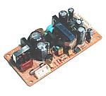 Input : AC100V Output : 12V-1A, 5V-2A |
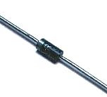 This diode is used in order not to pass current except a receiving unit and a CPU unit at the time of the battery use for backup. |
|||||||||||||||||||||||||||||||||||||||||||||||||||||||||||||||||||||||||||||||||||||||
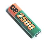 The rechargeable battery of 2500mAH is connected to 6 series. |
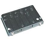 I used a plastic case. |
|||||||||||||||||||||||||||||||||||||||||||||||||||||||||||||||||||||||||||||||||||||||
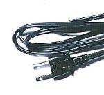 A vinyl cable with the AC plug is used. |
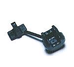 It is used in order to prevent contact of a power cable and a case. |
|||||||||||||||||||||||||||||||||||||||||||||||||||||||||||||||||||||||||||||||||||||||
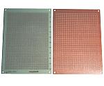 Universal printed board with 55 x 40 halls is used. Universal printed board with 55 x 40 halls is used.As the board which LEDs are mounted, cheap paper epoxy board is used. The glass epoxy board is used for the circuit. |
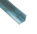 A large-sized LED is mounted on more than one printed board. The L angle which is made of aluminum is used to connect those printed boards. A large-sized LED is mounted on more than one printed board. The L angle which is made of aluminum is used to connect those printed boards. |
|||||||||||||||||||||||||||||||||||||||||||||||||||||||||||||||||||||||||||||||||||||||
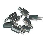 A circuit board is installed in the back of the LED board. In order to make the space of wiring, the 10mm stud is used. A circuit board is installed in the back of the LED board. In order to make the space of wiring, the 10mm stud is used. |
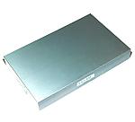 YM-400 which is made by the TAKACHI Inc. is used. YM-400 which is made by the TAKACHI Inc. is used.400mm(W), 250mm(H), 55mm(D) |
|||||||||||||||||||||||||||||||||||||||||||||||||||||||||||||||||||||||||||||||||||||||
 This strap is used to prevent the fall of the battery. This strap is used to prevent the fall of the battery. |
 This chain is used to hang a clock on the wall. This chain is used to hang a clock on the wall. |
|||||||||||||||||||||||||||||||||||||||||||||||||||||||||||||||||||||||||||||||||||||||