Parts explanation of Radio Controlled Clock
Most of the resistors and capacitors which are used for the kit are chip type.They are not introduced here.
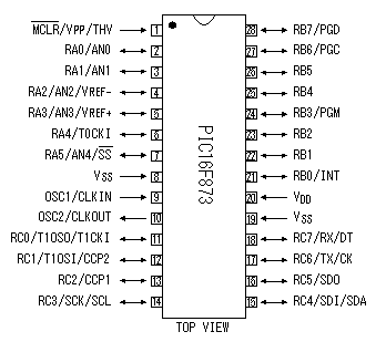 PIC16F873 is used for the main unit of radio controlled clock. The confirmation of the radio wave condition, processing the year/month/day/hour/minute/second and a display in the LCD are done by this IC. Also, it has four kinds of timer functions. |
|
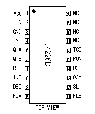 This is the exclusive use IC to take out the time information which is carried in the radio wave of 40KHz. At the data sheet, a radio clock system in some countries is introduced. |
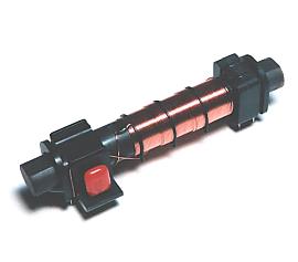 This is the bar antenna to receive the radio wave of 40KHz. |
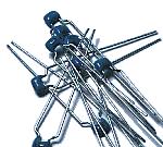
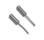 These crystal oscillators are used to receive the radio wave of 40KHz, being connected with receiver IC(U4226B). |
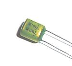 In order to carry out operational stability of the receiver circuit, the capacitor of high capacity accuracy is required. |
 This is also used for a receiver circuit. |
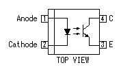 The kit is designed so that a receiver circuit and a display control circuit can be installed in a different place. They are connected by a cable. Therefore, the photo coupler is used for the signal drive. |
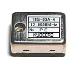 This is a high precision crystal oscillator for displaying exact time, even when a radio wave stops. Oscillation frequency is 12.8MHz. |
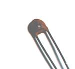
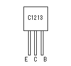 This transistor is used for the LED drive, the external circuit drive, etc. |
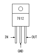
 This is a regulator for making the power supply (+5V) of a display control circuit. |
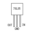 This is a regulator for making the power supply (+5V) of a receiver circuit. |
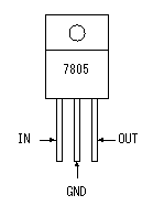
 This is a regulator for setting to stable +12V direct current voltage made with the transformer and the rectifier. |
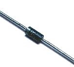
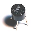 This is a diode bridge for rectifying alternating voltage to a direct current. 1A type is used. |
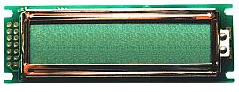  This is a liquid-crystal-display panel (LCD) for displaying time. This is a liquid crystal display made by SUNLIKE Co. in Taiwan. The display of two lines can be performed by 16 characters per line. |
|
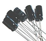 These capacitors are used in order to stabilize the supply voltage of a circuit. |
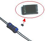
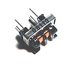 This is a coil for removing the noise generated when a receiver circuit and a display control circuit are connected by a long cable. |
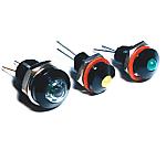 Right-hand side green LED is for the display of a receiving state. Central yellow is for the display of a second. Left green LED makes it blink by the TCO signal of a receiver. Right-hand side green LED is for the display of a receiving state. Central yellow is for the display of a second. Left green LED makes it blink by the TCO signal of a receiver. |
 These are LEDs which display the drive state of four timer circuits. |
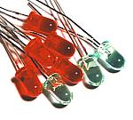 These LEDs are used in order to check the operating state of a circuit. |
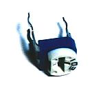 This is a variable resistor for adjusting the display contrast of LCD. |
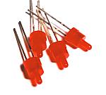
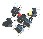 This clock has a function to control the outside circuit when becoming a set time. These switches are used in order to set up the time. This clock has a function to control the outside circuit when becoming a set time. These switches are used in order to set up the time. |
 This capacitor is used in order to suppress the oscillation of 3 terminal regulator used in the power unit. This capacitor is used in order to suppress the oscillation of 3 terminal regulator used in the power unit. |
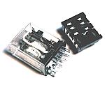 A relay is used to drive equipment outside with the timer. The drive voltage is 12 V and contact capacity is AC 100V/10A. |
 This diode is used in order to prevent the reverse current in a power supply unit. Also, this is used for protecting a drive circuit with the counter-electromotive force generated in operation of a relay. The type is 100V.1A. This diode is used in order to prevent the reverse current in a power supply unit. Also, this is used for protecting a drive circuit with the counter-electromotive force generated in operation of a relay. The type is 100V.1A. |
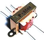 This is the transformer which secondary output is AC12V / 150mA. About 17V DC voltage will be made by full wave rectifying with the diode bridge. |
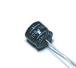
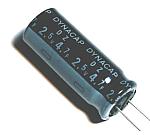 This capacitor is used as power supply backup when AC power supply stops. The specification of one capacitor is 4.7F/2.5V. Five pieces are connected in series and the electric strength is raised to 12.5V. The whole capacity decreases to one fifth and is 0.94F. When the capacity is expressed with micro Farad, it is the capacity of 940,000 µF. It is huge capacity. This capacitor is used as power supply backup when AC power supply stops. The specification of one capacitor is 4.7F/2.5V. Five pieces are connected in series and the electric strength is raised to 12.5V. The whole capacity decreases to one fifth and is 0.94F. When the capacity is expressed with micro Farad, it is the capacity of 940,000 µF. It is huge capacity. |
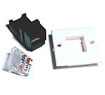
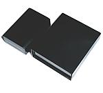 As the case of clock SY-150B made by TAKACHI electrical machinery industry is used. It's the case with a width of 150mm, a height of 54mm, and a depth of 170mm. As the case of clock SY-150B made by TAKACHI electrical machinery industry is used. It's the case with a width of 150mm, a height of 54mm, and a depth of 170mm.As the case of receiver PR-140B made by TAKACHI is used. It's the case with a width of 140mm, a height of 45mm, and a depth of 90mm. |
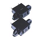 These are output plug sockets for AC. |
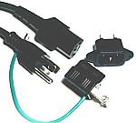 This equipment is designed to control a maximum of 1000W equipment. Therefore, 10A type cable is used for the power cable. |
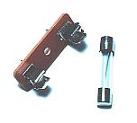 This is the fuse for power supplies of a radio controlled clock. It is 1A type. It has not equipped with the fuse for the load controlled by this equipment. |
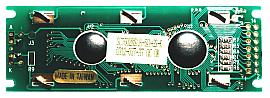
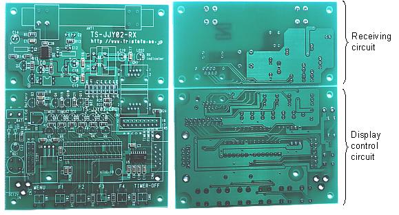 As for the printed circuit board of a kit, the receiving section and the display control section are drawn on the printed circuit board of one sheet. The receiving section and the display control section are separable. The first, I assumed that a receiver circuit was given on the display processing circuit. However, I found that the reception circuit must be adjusted to the direction where the radio wave comes. Therefore, I decided to put a clock display circuit and a receiver circuit in the different cases and connect them with the cable. |
|
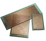 The universal printed circuit board is used for the power supply circuit and to mount the parts included an LCD in the front panel. |
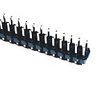 This is used as the terminal of the wiring with the parts which are installed outside the printed circuit board. |
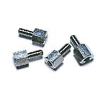 This metal stud is used to fix a printed circuit board on the case. |
 This is used as the terminal of power unit. |
 A left-hand side resistor is charging current control resister for Electric Double Layer Capacitor of a power circuit. It is the metal film resistor of 1W. A left-hand side resistor is charging current control resister for Electric Double Layer Capacitor of a power circuit. It is the metal film resistor of 1W.A chip type resistor is for back light current control of LCD. |
 This is the capacitor for ripple filter of a power circuit. This is the capacitor for ripple filter of a power circuit. |
 RJ-45 connector is used for the cable connector of a receiver and a display processor. | |