 7 segment LED latch circuit 7 segment LED latch circuit
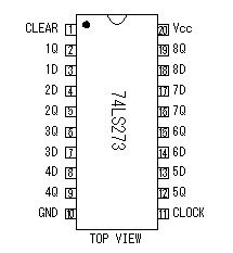
74LS273 which is D-type flip-flop (D-FF) as the latch register to hold the display of the LED is used. Eight D-FFs are housed in one piece of IC. One 74LS273 is used to control one 7 segment LED. I will show you how to use D-FF briefly. It inputs the data to D terminal to make hold. After that, it makes clock terminal (CK) H from L. By this, the condition of input (D) is held by output (Q) . The condition of the Q is held even if CK is made L. The timing that the condition of the Q is held is when CK changes into H from L. In the software of PIC this time, the CK is made L condition before the next digit is conrolled. But, the CK of the controlled digit can be made to L condition when the next digit is controlled.
The operation of the circuit this time is shown below. First, the data for the 100th is outputted to RB6 from RB0 and it is inputted to all the latch registers. Next, RA0 is made H and only the CK of the latch register (IC5) for the 100th is made H level. By this, a 100th digit is displayed in LED1. After that, the CK of IC5 is made an L level. In this condition, even if input (D) is changed, the condition of the Q doesn't change. Next, the data for the 10th is output to RB0-RB6. This data is inputted to all the latch registers but if the CK isn't made H, the Q doesn't change. In this condition, only the CK of the latch registers (IC6) for the 10th is made H level by the RA1 being made H level. By this, the 10th degit is displayed in LED2. Because the CK for the 100th LED isn't made H, the display contents of LED1 isn't changed. It is same in 1st disit.
It puts resistors in the cathode of the LED and an electric current is suppressed. The maximum electric current of the LED which was used this time is 25mA. An electric current is made about 22mA by the 100-ohm resistor.
"D" of D-FF is Delay. I think you can understand the reason for being called "D" by the animation which was shown above.

All Qs are made an L level when CLEAR terminal is made an L level. Because to initialize the held condition isn't necessary at the circuit this time, the CLEAR terminal connects with the Vcc terminal and always makes H level.
The condition of the D terminal is held by the Q terminal when the CLOCK terminal is changed into the H level from the L level. Even if the D terminal is changed in the condition except it, the condition of the Q terminal isn't changed.

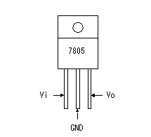
One 74LS273 consumes about 30mA electric current. At the circuit before improvement, 100mA type 78L05 was used as the 5V regulator. However, because the current capacity exceeded, it was modified into 7805 of 1A type.
|