 Microprocessor (PIC16F873) Microprocessor (PIC16F873)
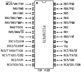
The receiving the data from console unit and displaying control of them are done by PIC16F873.
|
 4-16 decoder (74HC154) 4-16 decoder (74HC154)
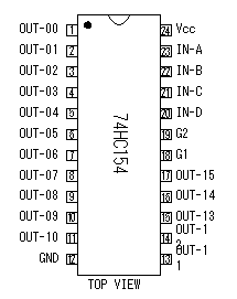
This is the IC which decodes the binary code of 4 bits.
16 conditions are indicated by 4 bits.74HC154 makes the output which corresponds to input's 4 bits an L level.
|
 RS-232 Drivers/Receivers RS-232 Drivers/Receivers
(ADM232AAN)
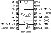
This is ADM232AAN of the ANALOG DEVICES Inc.. In this IC, 2 circuits of driver and 2 circuits of receiver are housed.
This IC has the DC-DC converter to make the voltage of +10V and -10V from +5V. So, the voltage of the RS-232C (about ±9V) can be made only with +5V power.
|
 Voltage regulator (78L05) Voltage regulator (78L05)

This is the IC to make +5V with +12V power. The output current of this regulator is 100mA.
Because to supply a power with this regulator is only IC's circuit, it is enough if there is 100mA capacity.
|
 IC socket IC socket
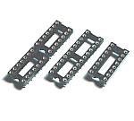
PIC16F873 is the IC with 28 pins of the slim type. When the slim type 28 pin socket can not be gotten, you can use two sockets of 14 pins. I did like this to the circuit this time. |
 PNP type transistor (2SA1015) PNP type transistor (2SA1015)

This transistor is used for the lighting-up control of the LEDs. PNP type is used when controlling LEDs on the side of the power. The circuit this time is using +12V for the power of the LEDs. So, PIC can not control an LED directly. It is controlled by the combination in PNP-type and NPN-type.
|
 Resonator Resonator
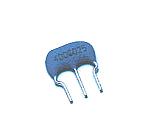 This is the oscillation device to make the clock of PIC. A ceramic vibrator and capacitors are incorporated. This is the oscillation device to make the clock of PIC. A ceramic vibrator and capacitors are incorporated.
The clock frequency this time is 4 MHz. It is possible to make do the operation of PIC16F873 with the a maximum of 20MHz clock. |
 NPN type transistor (2SC1815) NPN type transistor (2SC1815)

This transistor is used for the lighting-up control of the LEDs. The voltage which can be controlled in PIC is +5V. So, it works as the voltage change by LED control voltage (+12V) and PIC(+5V), too.
|
 Multilayer ceramic capacitor Multilayer ceramic capacitor
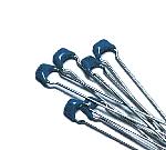
These capacitors are used for the DC-DC converter of RS-232 Drivers/Receivers and the high frequency bypass capacitor of the power circuit.
|
 Switching diode ( 1S1588 ) Switching diode ( 1S1588 )
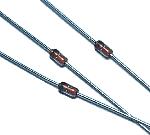
A switching diode is used for the lighting-up control of the LEDs for the category. The about 10mA electric current flows through an LED. The forward direction maximum electric current of this diode is 30 mA. |
 Printed board Printed board
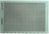
Universal printed boards with 55 x 40 halls are used.
The lead wire interval of the LED is the same as the hole of the printed board at 0.1 mm. However, the lead wire has sometimes come to the end of the printed board when mounting LEDs. So, the way of mounting LEDs needs consideration. |
 Resistor Resistor
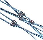
As for the resistor, all 1/6W are used. |
 Large-sized 7 segment LED Large-sized 7 segment LED
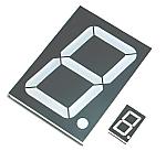
For the displaying, a large-sized 7 segment LEDs are used. The size of this LED is 12-cm height and 9-cm width. The size of character is 10-cm height and about 8-cm width.
The small LED which is put in the right is the LED which is used for the console unit. |
 LED for the category display LED for the category display
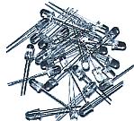
The LEDs which are arranged like a matrix is used for the category display. It is 11 rows(horizontal side) and 13 lines(vertical side). Total 143 LEDs are used. There are some LEDs which aren't lit up, too. I considered the change of the future and mounted all.
 |
 DSUB connector DSUB connector
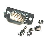
The serial cable of the DSUB9 pin is used for the connection between the console unit and the display unit. Because the power of the display unit is supplied from the console unit, a male connector is used for the side of the display unit.
|
 Case Case
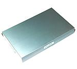
YM-400 which is made by the TAKACHI Inc. is used.
The size has 400-mm width, 250-mm height and 55-mm depth.
|
 Wiring connector Wiring connector
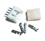
A display circuit is mounted into the cover of the case and DSUB connector is mounted on the body of the case. Therefore, it considers maintainability and a connector is used for the wiring. |
 Metal fittings for Display panel Metal fittings for Display panel
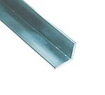
A large-sized LED is mounted on more than one printed board. The L angle which is made of aluminum is used to connect those printed boards. |
 Stud Stud
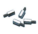
This stud is used to put a control unit and a diode matrix to the display panel.
10-mm length is used. |
 Connecting cable Connecting cable
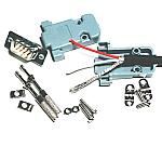
The screened cable which had 2 wires is used for the cable of the console unit and the display unit. Plugs with the DSUB connector are installed at the both edges. |