Circuit explanation of Console unit
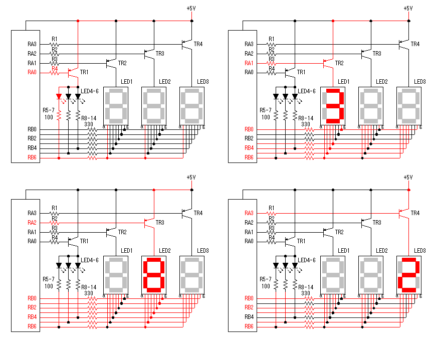 In the console unit, an LED for category display and three 7 segment LEDs are used. These LEDs are controlled one by one in the order by PIC. In case of this method, because only 1 digit lights up at the same time, so, the electric power is cut down. The power unit becomes small too. This control is done at high speed, so, it seems to light up at the same time to the look. In the console unit, an LED for category display and three 7 segment LEDs are used. These LEDs are controlled one by one in the order by PIC. In case of this method, because only 1 digit lights up at the same time, so, the electric power is cut down. The power unit becomes small too. This control is done at high speed, so, it seems to light up at the same time to the look.PNP type transistor is used to control of LED. The 7 segment LED which was used this time is an anode common type. Therefore, the transistor for the control must be put between the power and the LED. When the control port (RA0-RA3) of PIC becomes an L level, the transistor becomes ON and the corresponding LED becomes a lighting-up possible condition. A lit segment is decided by the condition of RB0-RB6. The LED segment lights up when the corresponding port becomes an L level. 100 ohm is used for the control resistor of the LED for the category display. Only one LED is written as LED4-6 on the schematic. However, three LEDs are connected each in parallel. To pass an about 10mA electric current to each LED, it should pass the electric current of 30mA in total. So, it becomes (5V-2V)/30mA=100ohm. 2V is the voltage which is applied to the LED. The voltage to apply to the LED is 5V. This is because the voltage which is applied to the terminal of PIC is 5V. The circuit which makes the voltage to apply to the LED more than 5V is used in the display unit. 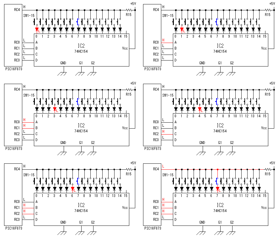 15 switches are used for the console unit. PIC scans a switch in the order and detects a pushed switch. 4-16 decoder is used to specify the switch to scan. 15 switches are used for the console unit. PIC scans a switch in the order and detects a pushed switch. 4-16 decoder is used to specify the switch to scan.In the binary signal of 4 bits, 16 kinds of conditions can be expressed. This decoder develops the binary signal of 4 bits and makes a corresponding signal port in 16 kinds of signals an L level. The detection of the switch operation is done in RC4. When neither switches are pushed, RC4 is H level with R15. In the following explanation, it supposes that SW-8 was pushed. When RC3, RC2, RC1, RC becomes 0111(RC3 is a higher rank bit), the terminal which SW-8 is connected becomes an L level. RC4 becomes an L level too because SW-8 is pushed. By this, SW-8 is recognized to have been pushed by PIC. The scan of the switch is done in order from SW-1 to SW-15 and repeats the operation which returns to SW-1 again. When detecting the switch of ON in the software of the switch scan, it doesn't scan the switch after that and it returns to SW-1. By this operation, only the switch which is near SW-1 is detected even if more than one switch is pushed at the same time and a malfunction is prevented. At the switch, the chattering phenomenon which repeats ON/OFF in short time occurs. A malfunction by this is prevented by the software too. The diodes between the switch and IC2 are to prevent electric current's flowing through the L level terminal from the H level terminal of IC2 when more than one key is pushed at the same time. 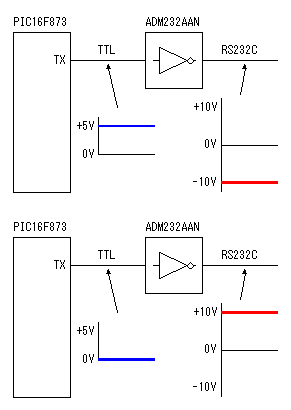 A RS232C interface is used to transmit the information which was set at the console unit to the display unit. A RS232C interface is used to transmit the information which was set at the console unit to the display unit.This interface is used for an interface with the modem. About ±9V is used for signal voltage on the connection cable with the display unit and the long distance transmission is possible comparatively. In the standard, the cable with about 15m length can be used. Actually, it is possible to use for any more distance. It depends on the condition of the cable. The +5V signal of PIC can be directly transmitted without using the RS232C interface if being a short distance. The purpose that this IC is used this time is to attempt to use the RS232C device and to secure a distance. In ADM232AAN of the ANALOG DEVICES Inc. which was used this time, it has the DC-DC converter which makes the voltage of ±10V with +5V power. So, the external circuit is very simple. 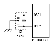 To make do the operation of PIC, a clock generator is needed. To make do the operation of PIC, a clock generator is needed.An oscillation circuit is had within PIC, so, it puts a vibrator outside only. As the vibrator, the crystal oscillator can be used because of the precision oscillation. However, at the circuit this time, a ceramic vibrator (Resonator) is used because it doesn't need the precision oscillation. The maximum clock frequency of PIC16F873 is upto 20MHz. However, at the equipment this time, because it doesn't need high-speed operation, the oscillation frequency is 4MHz. A transmission speed is calculated by 4MHz. So, when using this equipment at the clock frequency which is not 4MHz, reconsideration is needed. 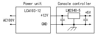 DC12V is made with AC100 by the switching power unit. At the console controller, a 3 terminal regulator is used to get +5V voltage from the +12V power. DC12V is made with AC100 by the switching power unit. At the console controller, a 3 terminal regulator is used to get +5V voltage from the +12V power.The regulator which is used this time is regulator for +5V. The merit of this regulator is low voltage dropout. In the specification, when the output current is 1A, the dropout voltage of this regulator is 0.5V. In the circuit this time, it makes +5V from +12V. So, a 7V voltage drop is caused with the regulator. So, the merit of LM2940 isn't effective. When making 5V voltage with 6V power, this function is effective. At the circuit this time, 7805 can be used. The one is cheaper. I am using to confirm the convenience of LM2940. At the equipment this time, about 100 mA are used in the console unit and an about 150mA electric current is used in the display unit. The capacity of the power unit is enough capacity because it is a maximum of 900mA. |