Circuit explanation of Transmitter
|
The Colpitts circuit is used for the high frequency oscillation circuit.  The figure on the left is the basic circuit of the Colpitts oscillation circuit. Roughly oscillation frequency is found by the following formula. The oscillation frequency changes by the length of the wiring, the capacitance of the transistor and other condition. So, the way of making actually and ascertaining is realistic. This formula is a simplified formula and in the correct formula, the condition of the transistor is added.  Oscillation operation is done by dividing the voltage which occurs between the collector and the base by C1 and C2 and making it return to the emitter. 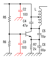 An oscillation circuit this time is shown on the left. 10000pF(103=10x103) is used for C2 and C3 of this circuit. The oscillation frequency of the circuit this time is about 83MHz. A 10000pF capacitive reactance (the resistance value with the alternating current) at 83MHz is shown below. 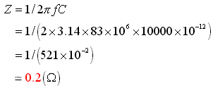 That is, there is little resistance when seeing C2 and C3 at the high frequency. It is in the condition which is the same when connected with the wire. 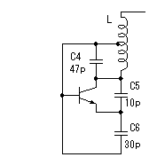 It becomes a figure on the left when seeing this circuit at the high frequency. As for this circuit, C4 is connected with the L in parallel but you find that it is Colpitts oscillation circuit. The calculation of the value of coil (L) was difficult and this time, I decided it by the cut & try. I decided an oscillation frequency on 83 MHz which don't overlap with the frequency of FM broadcasting station. There is no problem at the other frequency if not overlapping with the strong electric wave. The coil to be using this time is using the one to have wound a tin plating wire with 0.6mm diameter around the stick (the screwdriver) with 4.6mm diameter seven times. I make a tap (the node of the power) at the position of 4.5 turns from the side which connects with the collector. The position of this tap is my sense. As for this position, the supply of the high frequency electric power to the amplifier of the following stage is considered. The adjustment of the oscillation frequency is done by C4. The frequency fine control can do by expanding or crinkling a coil. It dosen't need to touche this coil basically after adjustment. The frequency changes when a coil is transformed by the vibration and so on. I used the a little thick diameter of 0.6mm for the wiring material of the coil to prevent the change of the frequency by these phenomena. In case of the high frequency circuit, the wiring becomes the part of the coil. So, when picturing the pattern of the circuit, the wiring that the high frequency passes makes it as short as possible. This is the circuit which amplifies the signal to have made with oscillator. An antenna is put to emit an electric wave. When putting an antenna to the oscillator directly, the position of the antenna and so on change an oscillation frequency. This amplification circuit is doing the function which prevents the operation of the oscillation circuit from the situation of the antenna, too.
As the circuit which receives the signal of the oscillator, generally, the high frequency transformer which has the 1st coil and the 2nd coil is used. In the circuits which I made, it is making do the function of the transformer with one coil. The signal can be transmitted to the power amplifier only with one coil because the base of the oscillation circuit transistor is grounding potential on the high frequency. 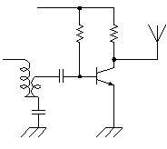 This power amplification circuit is a very simple circuit. It applies a few electric currents to the base and it makes the amplifier which is near a class "B" amplification. When handling high frequency, to make a class "A" amplification isn't necessary. It had better put a tuning circuit to the collector, too. However, the circuit this time omits for a circuit to be simplified. When emitting an electric wave, the output is prescribed in the electric wave law. I think that there is no problem of the electric wave law because the electric wave which it is possible to emit with this circuit is very feeble. Please examine electric wave law in your country. The control code does the electric wave of the transmitter to the control of ON/OFF. At design first, I examin the adoption of the frequency modulation (FM) method by the control code. However, I adopted an electric wave ON/OFF method because the circuit was simple. 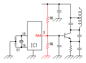 A control code is controlled by the software of PIC. With this, the control code can be easily changed. There are two purposes in this control code. A control code is controlled by the software of PIC. With this, the control code can be easily changed. There are two purposes in this control code.The 1st is to secure security. The FM electric wave which was modulated at the single frequency can be made with the other equipment, being easy. At the circuit this time, a control code with byte(8bits) is used. To recognize a control code, to detect a specific signal in front of it is needed. Also, it makes not recognize a normally control code when not detecting a normally signal more than one time. The 2nd is to change the kind of the control. The kind to control are designated by the contents of the byte. At the circuit this time, only two kinds of codes are used. More kinds can be controlled if changing the input circuit of the control. The operation (the oscillation/the stop) of the oscillation circuit is controlled using the RA4 port of PIC. It is because the RA4 port is an open type. As for the other port, at the time of ON (the H level), +5V are output and at the time of OFF (the L level), 0V are output. As for RA4, at the time of ON (the H level), output is only separated from the grounding and voltage isn't output. So, it becomes the condition which is the same as PIC's not being connected when seeing from the oscillator and the oscillation circuit does oscillation operation. When RA4 is OFF (the L level), 0V are output. Because the base of the oscillation circuit is grounded when RA4 becomes 0V, the oscillation stops. 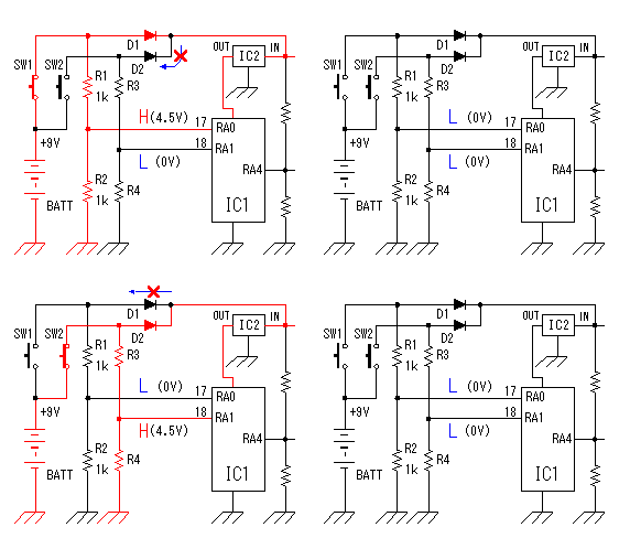 The operation of the circuit of the transmitter only when pushing a control switch. When a control switch isn't pushed, it makes all circuits stop. When a control switch isn't pushed, it makes all circuits stop to suppress the consumption of the battery cell. The control switch combines the selector switch of the control code and the power switch. A control switch is connected with the side of the positive of the cell and a power is supplied to the circuit even if it pushes any switch. Control code selection malfunction is prevented by the diodes. I used a +9V dry battery for the power of the transmitter. This dry battery is called 006P in Japan. Maybe this dry battery is called as 1604(NEDA) or 6F22(IEC). Anyway, this is 9V dry battery for transistor radios. The voltage for PIC is converted to +5V with the 3 terminal regulator. The voltage of the dry battery falls in consumption of the electric power. When the power supply voltage changes, the oscillation frequency of the Colpitts oscillation circuit to be using this time changes. Even if the transmission frequency changes little, the receiver can detect an electric wave. So, it isn't using a stabilization voltage circuit for the oscillation circuit. However, when the voltage of the dry battery falls extremely, the oscillation frequency of the transmitter becomes the detection impossible condition with receiver. PIC needs to make the voltage of the power and all input-output ports equal to or less than +5V. The parts (RA0,RA1 and RA4) which connects with the +9V circuit makes less than +5V. |

