Circuit explanation
of Light controller
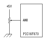
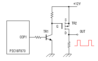
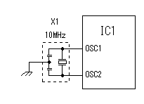
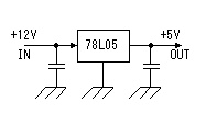
 The control voltage is changed from 0V to +5V by variable resistor. The voltage is inputted to the analog port of PIC. In this circuit RA0/AN0(pin13) is used for the analog input port. Because it isn't using VREF+ and VREF-, the minimum of the A/D conversion is Vss=0V and the upper limit is Vdd=+5V. The value of the variable resistor can be decided as you like. I used the B type of 10K ohm. The control voltage is taken in at the 1-millisecond period by CCP2 to work as compare mode. For the details of the CCP, refer to "CCP feature of PIC16F873".  The electric current which flows through the lamp is controlled by switching MOS FET. Because 2SJ471 which was used this time can pour in a maximum of 30A, it can control in about 300W. However, to control in 300W, it is necessary to consider including the thickness of wire, the radiation so on. In this equipment, I aimed at controlling about 100W. Because the operating voltage of PIC is +5V, a transistor is used to control MOS FET with 12V. A lamp is controlled by the PWM(Pulse Width Modulation) operation of CCP1. For the details of MOS FET, refer to "MOS FET". For the details of the CCP, refer to "CCP feature of PIC16F873".  I am using 10-MHz resonator.  3 terminal regulator is used to get the operating voltage of PIC. I used a 100 mA-type regulator. |