Software for Signboard 2
[Set Data]
|
This routine sholud be put on the main process.
In this processing, LED control isn't done. This processing is used with the other display effect processing.
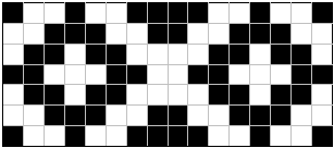
In the signboard, I made memorize the data to display in the EEPROM. In the case, the data which can be stored is a maximum of 64 bytes. The program memory has the capacity of 1K Words. So, it is possible to make store more data. But, because a program is stored in the memory, it isn't possible to use all memories for data. Because 1 Word is composed of 14 bits at the program memory, it isn't possible to make store data with byte(8 bits) just as it is. Therefore, I am handling data with byte using the RETLW instruction. RETLW is the instruction to use when returning from the subroutine. When returning, it stores data with the byte which was specified by the instruction into the W register. So, the data can be gotten if reading W register when returning from the subroutine. In the routine this time, DATA1_READ is a subroutine for the data reading. In this processing, it adds an index to the address at the head of data table (DATA1) and it jumps. The address of the program memory is specified by PCLATH(For higher 5 bits) and PCL(For the lower 8 bits) of SFR. PCL can specify only an address from 0 to 255(FFh) because it is a byte. In case of more than 255 address, PCLATH is set. It doesn't need to be conscious of PCLATH if the data table is within address 255. The fact is not only such a case. When calculating a jump address, it adds an index to PCL. After that, it checks a carry and it adds 1 to PCLATH if there is a carry. It jumps by rewriting PCL to the calculated address. As for being careful when handling PCLATH, the set value is not to change even if the execution address of the program becomes within 255. For example, the head address of DATA1 assumes 250 and the end address assumes 265. When doing the calculation which jumps to the end address of the data [250(FAh)+15(Fh)=265(109h)], PCL becomes 09h because it is a byte. It adds 1 to PCLATH because the carry occurs. The value of PCLATH is as 1 even if the execution progresses and the execution address of the program becomes within 255. Once again, it is as 1 when a data setting subroutine is executed, too. When processing just as it is, a different address has been calculated. Therefore, it sets the higher bits of the head address of the data table to PCLATH once again at the head of data reading subroutine (DATA1_READ). As for the composition of the data table, the head is the left end of the display and the end is the right end. Also, bit 0 is upper end and bit 6 is the bottom tip. As for the setting data, '0' shows lighting-up and '1' shows going-out. Bit 7 isn't used. RB7 is for the specification of the direction of the turn of the edge LEDs and the value of the data table isn't used. When you make the other data, the labels of the subroutine must be changed every subroutine. You must be careful so as not for the label to duplicate. You need to change the red figure on the list. To save a memory, there is a way of making the routine as the data table can be switched by the index, too. The 31th line and the 32nd line can be written by 1 line as follows, too. The assembly result is the same. (The 2 instructions are made) addcf pclath,f ;PCLATH + Carry The display pattern of above-mentioned list is as follows.
 |