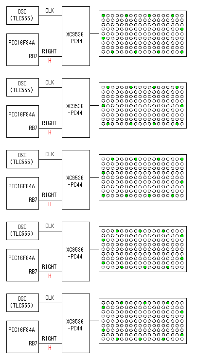
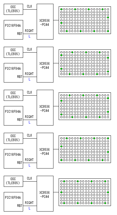
Circuit explanation of signboard 2
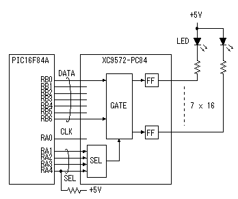 The lighting-up condition of the LED is held with the latch register of CPLD. The lighting-up data of 7 bits(For one row) is output from PIC. A row is specified by the RA port. Latch of the data is done in the falling edge of the clock signal which is output from RA4. Two XC9572-PC84 are used for 112 LEDs to latch. RA4 is different from the other RA ports and must put a pull-up resistor outside.
Ornamental LEDs are put around the LEDs for displaying message. The 5 binary counter which is constructed in XC9536-PC44 is used. The direction of lighting-up movement where the LED lights up is shifted by the clock signal from the OSC. The direction is changed by the level of RB7 of PIC. When RIGHT is an L level, it is counterclockwise. CPLD of the XC9500 series can be applied 24-mA current for one pin. So, two LEDs can be controlled with one pin. The number of the LEDs is 50. So, it is used five sets of output of the 5 binary counter. The animation on the left is equivalent when using a clock signal with about 200-millisecond period. 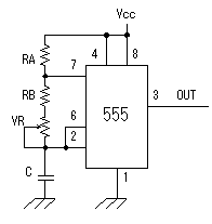 This oscillator generates clock pulse for edge LEDs. The shifting speed can be adjusted with the variable resistor.
At this circuit, they are RA=1.2K-ohm, RB=3.3K-ohm,VR=20K-ohm and C=100uF. So, the oscillation frequency is as follows.
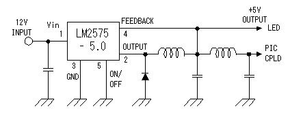 The voltage which is applied to the terminal of CPLD is upto 5V. So, the voltage of the LED must be made 5V too. The current of each LED is 10 mA. So, when all LEDs light up, the total current is about 1.2 A. At this equipment, an AC adapter is used to make a power unit compact. Because 12V/1A (12-W type) could be cheaply obtained, I used 5V voltage switching regulator. For the power to PIC and CPLD, the 2nd filter is used. This filter is put to reduce the ripple. This switching regulator circuit is the circuit to be introducing on "+5V Switching regulator (1)". The maximum current of LM2575 is 1A. When all LEDs are lit up, the required current is over 1A. But if not making all LEDs is lit up for long time, there is no problem. |
|||||||||||||||||||||||||||||||||||||||||||||||||
