 IC for the clock oscillation ( TLC555 ) IC for the clock oscillation ( TLC555 )
 This IC is used to make oscillate a 1-Hz square wave. This IC is used to make oscillate a 1-Hz square wave.
I make a clock 1 Hz to confirm the operation of the logic with the eyes.
The wave form of the output pulse of the oscillator rather depends on the IC to use. A normal test isn't made when the rising edge, the falling edge of the wave form have disorder.
First I used NE555. However, because the counter malfunctioned, I changed into TLC555. The function is the same but seems rather differently in the characteristic. TLC555 is CMOS-IC.
IC socket
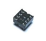
This is the socket which mounts IC for the oscillator. You may install IC in direct on the printed board.
LED for the output confirmation
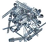
I used the LEDs of the high brightness type with 5-mm diameter.
I used 1K-ohm resistor which was inserted in series. The power supply voltage is +5 V and the voltage which is dropped by the LED is 2 V. So, the current of the LED is about 3V/1K-ohm=3mA.
DIP switch
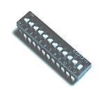
This is a switch with the DIP(Dual In Line Package) type of 12 bits.
BCD switch
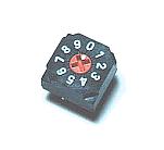 This is a small BCD switch. Common terminal (C) and the terminal of each bit are connected according to the binary-coded decimal code by turning a switch. This is a small BCD switch. Common terminal (C) and the terminal of each bit are connected according to the binary-coded decimal code by turning a switch.
7 segment LED
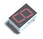 I used an anode common type. So, each segment lights up with the grounding through the resistor. I used an anode common type. So, each segment lights up with the grounding through the resistor.
Resistor
These resistors are used for the current control of the LED, the DIP switch pull up, the oscillator, and so on.

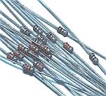
Countercurrent prevention diode ( 1S1588 )
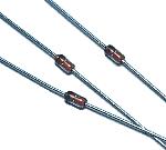
As for the BCD switch, more than one terminal is sometimes connected with the common terminal by the binary-coded decimal code. I put countercurrent prevention diodes so as not for the current to do flow among those terminals. When using only one BCD switch, it is not, being needed.
Capacitor for the oscillator
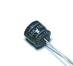
This capacitor is used as the capacitor for the oscillator.
LED for the oscillation operation confirmation
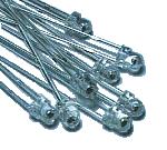
This is the LED to confirm the operation of the oscillator. An high brightness LED with 3-mm diameter is used for the LED.
Wiring terminal
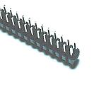
This is the terminal to connect with the CPLD programmer. I used a double type.
Printed board
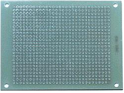
I used an universal printed board with 24 x 30 halls.
Stud
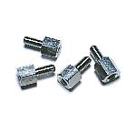
These studs are used as the leg of the printed board.
Connection cable
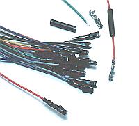
I made CPLD programmer connection cable with the code of the thin vinyl clothing.
The female pin has various types. I used the one of the cylinder which fits male pin.
I covered a pin with the tube which shrinks in the heat.
|