
 Input setting by the DIP switch Input setting by the DIP switch
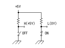
It is possible to do 12 kinds of input setting using the DIP switch.
The level of the terminal changes into the L level(0V) when the contact of the switch closes.
When the contact of the switch opens, the level of the terminal changes into the H level by the pull-up resistor.

 Square wave oscillator Square wave oscillator
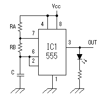
About 1-Hz square wave is generated by this oscillator.
When examining a counter, you need confirm the rising edge, the falling edge of the pulse sometimes.
The LED which is put to the output of the oscillator lights up by the H level of the pulse. By this LED, you can confirm the timing of the rising edge, the falling edge of the pulse.
The frequency of the oscillator can be calculated by the following formula.

| f | : | Output frequency (Hz) |
| RA | : | Resistor (ohm) |
| RB | : | Resistor (ohm) |
| C | : | Capacitor (F) |
|
At the circuit this time, they are RA=1.2K-ohm, RB=5.6K-ohm and C=100uF.
So, the oscillation frequency is as follows.
| f | = | 1.49 / (( RA + 2RB ) x C ) |
| = | 1.49 / (( 1.2 x 10³ + 2 x 5.6 x 103 ) x 100 x 10-6 ) |
| = | 1.49 / 1.24 |
| = | 1.20 Hz |
In the actual circuit, because of the error of the resistance, the capacitor and so on, it differs from the calculation value a little.

 Input setting by the BCD switch Input setting by the BCD switch
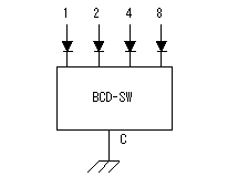 This circuit is used when setting in the BCD(Binary Coded Decimal) input. This circuit is used when setting in the BCD(Binary Coded Decimal) input.
By the position of the switch, the condition of each terminal changes as follows.
| Position | Terminals |
| 1 | 2 | 4 | 8 |
| 0 | O | O | O | O |
| 1 | L | O | O | O |
| 2 | O | L | O | O |
| 3 | L | L | O | O |
| 4 | O | O | L | O |
| 5 | L | O | L | O |
| 6 | O | L | L | O |
| 7 | L | L | L | O |
| 8 | O | O | O | L |
| 9 | L | O | O | L |
O : Open ( It is connected with nowhere. ) |
 Output confirmation by the LED Output confirmation by the LED
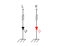
The output level of CPLD can be confirmed by the lighting-up of the LED.
When the output is H level, the LED lights up and in case of the L level, it goes out.
 Output confirmation by 7 segment LED Output confirmation by 7 segment LED
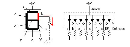 Because each segment of the 7 segment LED is connected with the terminal, the 7 segment LED control action by the CPLD can be confirmed. Because each segment of the 7 segment LED is connected with the terminal, the 7 segment LED control action by the CPLD can be confirmed.
Because the circuit this time used an anode common-type LED, it is possible to use only in case of the way of controlling which lights up by the L level.
In case of the way of controlling which lights up by the L level, the cathode common-type LED needs be used. |