[Menu]>[Application]>[Ultra High Accuracy Digital Clock]>[Production]
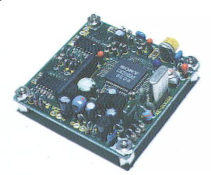

PLL oscillator


This is the oscillator that is the heart of the clock in this time.

The PLL oscillator is the device that stabilizes oscillation frequency by using the Phase Locked Loop circuit.
In the case of this time, the '10MHz standard frequency oscillator kit' that purchased with 'Akizuki Denshi Tsusho Ltd.'(Site in Japanese) is being used.

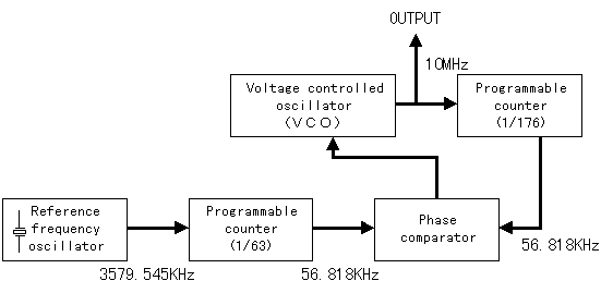
The crystal oscillator of 3.579545MHz is being used for the reference oscillator.
Dividing 63 this frequency 56.8181746KHz is made, furthermore doing it 176 times 9.999998729MHz is made. ( Error be the limit of my desk calculator )
Because it is making the significant figure below the decimal point of oscillation frequency 6 figures on calculation a little error has appeared.
Because it is the error of 1.27Hz to 10MHz accuracy becomes -1.27 x 10⁻⁷ and it assumed that it is delayed 1 second in 7,874,400 seconds.
Although it becomes the delay in 4 seconds for a year, it does not deviate much in fact.

This kit is sold with the style that summarized printed wiring board and necessary components.
All the components must be attached with hand work.
Especially soldering of IC ( CX20032 ) that is the main component of this circuit may be painful work for the unfamiliar person of soldering, because it is the SMT ( Suface Mounting Type ) with 42 pins.
Produce and utilize solder sucker etc.


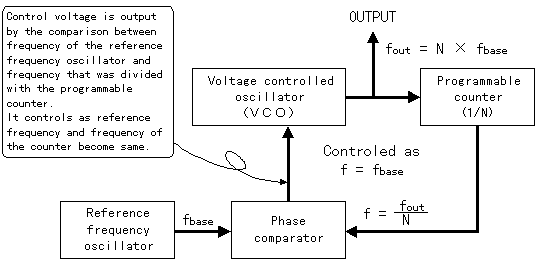
Principle of the PLL oscillator


Reference frequency oscillatorThe high stability oscillator like a crystal oscillator etc. are used.
Voltage controlled oscillator ( VCO )This is the oscillator that frequency changes by voltage control.
Phase comparator The comparative difference between reference oscillation frequency and output frequency is detected.
In the case that there is a difference the control voltage is output.
In the case that the output frequency is high the voltage that lowers frequency to VCO is output.
Programmable counter Dividing output frequency comparative frequency is made.
Output frequency can be changed by changing the counting value.


It becomes the frequency relation like the following in the PLL oscillator that uses it this time.


Furthermore reference frequency oscillator is being synchronized PLL to color burst signal of picture signal of the television in CX20032 that is using with '10MHz standard frequency oscillator kit'.


Action of the programmable counter

Time chart of the hexadecimal counter

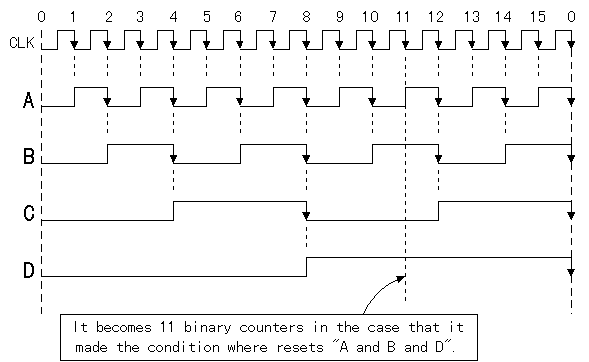
The figure of the top is showing the time chart ( Figure that expressed the voltage that changes with time ) of the hexadecimal counter.
The hexadecimal counter is composed of 4 pieces of 2 binary counters. Although input frequency is inserted into the 1st stage the output of the 1st stage is input into the 2nd stage. Output of the 2nd stage is input into the 3rd stage and output of the 3rd stage is input into the 4th stage.
Each stage the time when voltage changes becomes 2 times ( 1/2 for frequency ).
The timing of the counting up is carried out when the signal changed in the low level from high level.( Time when it showed with the arrow )
IC called 74HC393 is being used as the programmable counter in the oscillator that uses it this time. As for this IC 2 counters of hexadecimal are included in a package. There is a reset terminal in each counter and the counter becomes reset condition with high level( +5V neighborhood, It writes in H ).
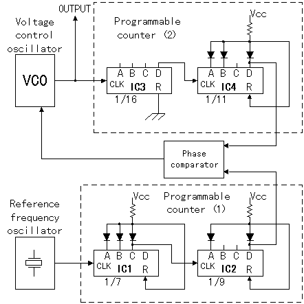
The circuit drawing of the right is the one that wrote the part of the programmable counter in detail.
IC4 is made an example it's operation is explained.
The cathode side of each diode is connected to output A of the 1st stage, output B of the 2nd stage and also output D of the 4th stage.
The anode side of the all diodes are connected to the reset terminal (R) of IC4 and they are connected to Vcc(+5V) through the resistor(4.7K ohm).
When any of A, B or D is a low level( 0V neighborhood ) the voltage of the reset terminal is pulled to a low level. The IC4 does not become to the reset in this condition, because the reset operation is done with high level.
In other words, only when all of A, B and D became high level the reset terminal becomes high level and the reset operation of IC4 is carried out.
When you see it on the time chart, the condition is when the 11th input signal become a low level from high level. The reset operation is carried out in this point and A, B, C and D become low level condition all.( Return to the starting point )

There is the following method to find where should A, B, C, D connect the diode to divide to required frequency easily.
First of all, A is made "1", B is made "2", C is made "4", D is made "8",and it is subtracting it to the big order from the required division number.
For example, In the case that you want to make 13 binary counters the calculation is 13 - 8 = 5, 5 - 4 = 1. It is up to here. This calculation as a result it assumed to connect the diodes to 8 "D", 4 "C" and 1 "A".
In the case of the programmable counter (1), 7 binary counters of IC1 become 1"A" + 2 "B" + 4 "C" = 7 and 9 binary counters of IC2 becomes 1 "A" + 8 "D" = 9.

In the case that the counter is reseted forcibly by the diodes, the time of low level and the time of high level of the output of counter(duty) are not equality. The time of high level becomes short.
In the case that duty of output becomes a problem the counters of 2 binary is used for the final stage. However, it needs to consider the division number, because it is divided to 1/2.

There is the description that does 'somewhere pin of somewhere IC is floated from the printed board' with the article of the reconstruction of the CPU clock.
For example when the terminal of A of IC1 is floated( same as remove the diode ) from printed board IC1 becomes 6 binary counters.
Although before reconstruction the frequency that is input to phase comparator is 3579.545KHz / 63 = 56.818KHz and final output frequency is 10MHz, after reconstruction the frequency is 3579.545KHz / 54 = 66.288KHz and final output frequency is 11.66MHz( +16.6% up ).
In the case of actual CPU circuit of the PC, IC that is using, reference frequency, the division number etc. are different from the example of the top. The principle is a similar thing.
But, phase comparator or VCO comes not to flatter when frequency is changed largely by the division number. I think that there is not an influence if it is a dozens %. But, when it is made 2 times, 3 times the VCO control signal from the phase comparator needs to be checked.