
 Inverter IC ( 74LS04 ) Inverter IC ( 74LS04 )
 This IC is power saving type inverter IC. (LS:Lowpower Shottky) This IC is power saving type inverter IC. (LS:Lowpower Shottky)
It isn't possible to use a CMOS-type inverter for this circuit. Because the electric current flows through the input of the inverter hardly, the electric charge of the capacitor doesn't run away.
LED control transistor ( 2SC1815 )
This is a transistor for the small signal amplification. This transistor is used for the lighting-up control of the LED.
The other transistor can be used if the collector permissible current is about 100mA and the hFE is about 100. Because the L level inflow permissible current of 74LS04 is 8mA, the LED can be controlled even if it doesn't use a transistor if suppressing an LED electric current with the resistor.
IC socket
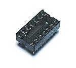
The IC can be directly soldered to the printed board. I considered the removal of the IC and used an IC socket. This is a socket for 14 pins.
Capacitor
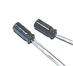
This capacitor is used to decide a repeat period. I used cheap Electrolytic Capacitors. The capacitor of the other type can be used if the capacity is same.
Light Emitting Diode
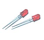
The light-emitting diode has various shapes.
You can select the type of your taste.
Diode ( 1S1588 )
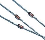
I used a switching diode. The diode for the rectification can be used because it is low-frequency.
Resistor
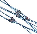
The resistor which is the type that the permission electric power is 1/8 W is used. The size of more than 1/8 W resistor is larger.
Stud
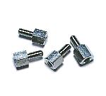
I used the stud as the leg of the printed board.
Wiring terminal
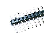
This is the terminal to connect a power.
Printed board
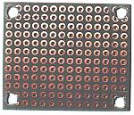
I cut an universal printed board according to the space of the circuit.
|