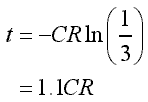
The time-out time is calculated by the following formula.
 t=time-out time(sec), C=Capacity(F), R=Resistance(ohm)
This formula can be found out as follows.
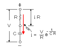
The electric current change when voltage (V) is applied to the circuit which capacitor (C) and resistor (R) were connected with in series is demanded by the following formula.
|
 |
| i | : Electric current which changes in the time(A) |
| V | : Applied voltage(V) |
| R | : Resistance value(ohm) |
| C | : Capacitor value(F) |
| e | : Base of the natural logarithm(2.71828) |
| t | : Elapsed time after the charging beginning(sec) |
| CR | : Capacitive time constant (C x R) |
|
The voltage change of the both edges of resistor (R) is demanded by the following formula.

The time when the voltage of the both edges of capacitor (C) becomes 2/3 of power supply voltage (V) is time-out time. That is, it is when the voltage of the both edges of the resistor becomes 1/3 of power supply voltage.
 The time (t) is as follows.

At this circuit, R is R1+VR.
The calculation result when VR is the minimum and maximum is shown below.
 VR=0 ohm (the shortest time) VR=0 ohm (the shortest time)
| t | = 1.1 x 100 x 10-6 x 100 x 103 |
| = 11 (sec) |
 VR=1M ohm (the longest time) VR=1M ohm (the longest time)
| t | = 1.1 x 100 x 10-6 x 1100 x 103 |
| = 121 (sec) |
The measurement result of the circuit which was made this time in the time-out time is shown below.
| VR=0 ohm (the shortest time) | : 13 seconds |
| VR=1M ohm (the longest time) | : 138 seconds |
Supposing that the error of the resistor is +5%, the error of the variable resistor is +10%, and the error of the capacitor is +10%, the longest time is as follows.
| t | = 1.1 x 110 x 10-6 x 1205 x 103 |
| = 145.8 (sec) |
The measurement time is the inside of the error range of the parts. |
|