Circuit explanation for +30V DC-DC converter
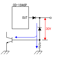
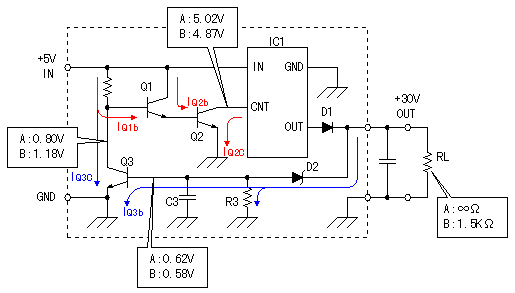
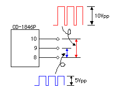
The step up operation of the voltage is done with the switching regulator (IC1). The external circuit includes the volrage control circuit. The Zener diode(Reference diode) for 30 V is used to keep the output voltage constant. The switching regulator is controlled by detecting the electric current which flows through the Zener diode. Strictly, the value which added the voltage of the Zener diode and the voltage between the base and the emitter of the transistor for the electric current detection becomes the output voltage.  When the load resistance decreases(The load current increases), the electric current which flows through D2 decreases. By it, the base electric current(IQ3b) of Q3 decreases. When IQ3b decrease, the collector electric current (IQ3c) of Q3 decreases too. Then, the collector voltage of Q3 rises. When the collector voltage of Q3 rises, the base electric current (IQ1b) of Q1 increases. When IQ1b increase, the collector electric current of Q1 increases. Q1 and Q2 are connected with the Darlington connection. So, when IQ2b increase, IQ2c increase too. When IQ2c increase(The collector voltage of Q2 falls), IC1 works to increase the output current. Because there is not data of IC1, I don't find the operation which is conversant. The control action to make the output voltage constant by above operation is done. When the load resistance becomes big, it works contrary to the above.  CD-1846P has the output terminal with the AC voltage. The signal of the switching operation is output to this terminal. So, the signal wave form is not the sine wave and is the square wave. Also, the duty is not 50% too. The frequency is changed by the load. It was about 780 KHz when measuring by the frequency counter. I think it is too high. There is possibility that the counter isn't measuring correctly. |