Performance measurement
of the thermostat
|
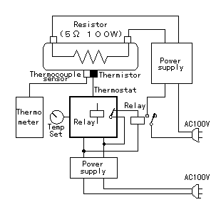
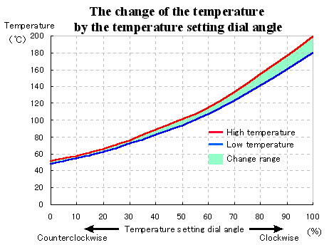
I will show the result which measured the relation with the axis angle of the variable resistor for the temperature setting and the temperature of the heating element which was controlled with the thermostat which was made this time below.  I used the wirewound resistor of 5-ohm 100-W as the heating element which is the same as the case to have measured the change of the thermistor resistance value by the temperature. I made the thermistor to control the temperature and the thermocouple thermometer sensor to do the thermometry touch the surface of the resistor by the point. The wirewound resistor is heated by the electric power from the stabilised power supply. The temperature of the resistor is controlled by ON/OFF of the AC input of the stabilised power supply by the output of the thermostat. The temperature change(Maximum temperature and the minimum temperature) at the specific temperature is changed by the quantity with the electric power which is supplied to the resistor, the thermal capacity of the heating element, the radiation quantity of the heating element and so on.  In the graph on the left, the blue line shows the temperature that the relay of the thermostat became OFF and the red line shows the temperature that the relay became ON. The temperature of the resistor continues to rise in a little time even if the power supply stops. The red line shows the temperature that the rise of the temperature stopped. In the graph on the left, the blue line shows the temperature that the relay of the thermostat became OFF and the red line shows the temperature that the relay became ON. The temperature of the resistor continues to rise in a little time even if the power supply stops. The red line shows the temperature that the rise of the temperature stopped.In the range which is shown in the green, the temperature repeats the rise and the fall. The range of the change gets widely when the provision with the electric power increases. When making the temperature setting maximum at the circuit this time, it becomes 180 to 200°C. There is fear with the degrading characteristic of the thermistor when applying this temperature to the thermistor long. I think that it had better make the setting possible range with the maximum temperature narrow by making the resistance value of R6 big a little. |