Circuit explanation
of the thermostat
I mention the point when I design a circuit this time below.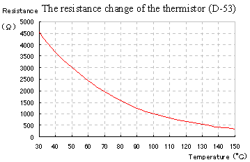 The thermistor which was used this time is D-53 which is made by NEC. D-53 is NTC(Negative Temperature Coefficient Thermistor)-type thermistor. It has the characteristic that the resistance value decreases when the temperature rises. I used this thermistor because it was possible to be obtained by chance by me. Because I didn't understand detailed data, first, I measured the change of the resistance value by the temperature change. As the heat source, I used the wirewound resistor of 100 W. This resistor was used as the loading resistor in case of the stabilised power unit making. When applying 65-W electric power to this resistor, the surface temperature becomes over 150°C. In the resistance value measurement this time, I raised a temperature in 150°C but there are many thermistors which make +100°C or +120°C the upper limit temperature in usual use. The one which avoided using continuously at more than +150°C is safer. Generally, the practicable temperature of the thermistor is referred to as follows. 150°C for short-term exposures (1-24 hours) 105°C for long-term exposures (1-12 months) Because a practicable range is decided by the thermistor, for the details, it had better confirm data. There is self generation of heat in one of the consideration points when using a thermistor. When applying an electric current to the thermistor, the heat occurs. In case of the NTC-type thermistor, when many electric currents occur, the generation of heat decreases a resistance value. The vicious circle of the increase of the electric current value and the decrease of the resistance value occurs. Because it is, the electric current to apply to the thermistor must be made necessary and minimum. The thermistor which was used this time has the resistance value of about 5 Kohm at 25°C. The electric current which flows through the thermistor at this time is about 0.55 mA(12V/(16Kohm+5Kohm+1Kohm)) and the consumption electric power becomes 1.5 mW((0.55mA)2 x 5Kohm). If being this value, there is no problem. The resistance value falls when the temperature rises and the electric current increases. However, because the resistor of 16K ohm is included, when the resistance value of the thermistor falls, the consumption electric power of the thermistor decreases. 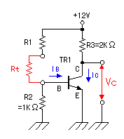 The figure on the left is the circuit which changes the change of the resistance value of the thermistor into the change of the voltage. It is the basic amplification circuit which used a transistor. The electric current which flows through emitter(E) from collector(C) changes when the electric current which flows through base(B) changes. A changing rate is shown at the current amplification factor(hFE=IC/IB). The hFE depends on the kind of the transistor and a class is sometimes divided in the transistor of the same name. The figure on the left is the circuit which changes the change of the resistance value of the thermistor into the change of the voltage. It is the basic amplification circuit which used a transistor. The electric current which flows through emitter(E) from collector(C) changes when the electric current which flows through base(B) changes. A changing rate is shown at the current amplification factor(hFE=IC/IB). The hFE depends on the kind of the transistor and a class is sometimes divided in the transistor of the same name.This time, the transistor which I used is 2SC1815(Y). At the data sheet, the hFE of the Y class is 120-240. As shown in this data, the hFE is different every transistor. At the circuit this time, the collector voltage (Vc) doesn't make be saturated in the change range with the resistance value (Rt) of the thermistor. I make the change range of Rt 5k ohm and I decide the proper value of R1. R2 is 1k ohm. (For the stabilization of IB, it is as stable as low. As for being too low, it is hopeless.) R3 is 2k ohm. (When TR1 is in the ON condition, about 6-mA electric current is passed.) The one which was measured in above condition is the following graph. 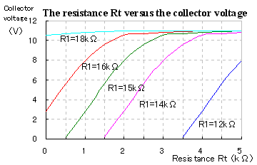 At the circuit this time, because I wanted to use the collector voltage without making it be saturated when Rt is less than 1k ohm, I decided the value of R1 on 16k ohm. I measured with the circuit which was experimentally assembled to decide the rough value of R1. After that, I measure once again after putting together a circuit finally and I do the adjustment which included the characteristic of the related parts, too. Because the voltage converter is an amplifier, the signal which was applied to the base is amplified and appears at the collector. The bypass capacitors are put in each part to make an influence by the unnecessary signal from outside little. Also, when the wire which connects with the thermistor and the voltage converter is long, there is possibility that an alternating current signal is led to the connection wire and that the converter malfunctions. Therefore, the shielded wire is used for the wire which connects the thermistor. At the circuit this time, the voltage comparator is used to detect whether or not the temperature which was detected with the thermistor becomes the setting temperature. It compares the output voltage of the thermistor voltage converter and the temperature setting voltage. When there is a voltage difference, by the condition of the difference, it does ON/OFF of the relay drive circuit. 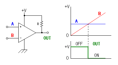 When the voltage of the positive terminal is higher than the voltage of the negative terminal, the inner transistor of the comparator becomes OFF condition (the H level condition). Then, when the voltage of the positive terminal is lower than the voltage of the negative terminal, it becomes ON condition (the L level condition). At the circuit this time, the voltage of the voltage converter is connected with the negative terminal of the comparator and temperature setting voltage is connected with the positive terminal. I am doing like this in the relation of the pattern of the printed board. This is OK even if it is opposite but the output of the comparator becomes opposite. 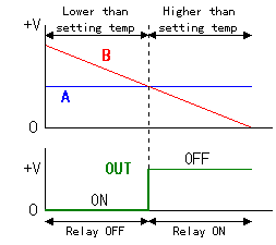 When the voltage of the voltage converter(the negative terminal) is high(the temperature is low), the output of the comparator becomes ON condition. Because it is, the relay doesn't work(S and B are connected). The output of the comparator becomes OFF condition when the temperature rises and the voltage from the voltage converter(the negative terminal) becomes lower than the temperature setting voltage(the positive terminal). With it, the relay becomes an operating state(S and M are connected). There are following purpose in the resistors to put to the both edges of the variable resistor for the temperature setting.
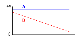 The output voltage of the voltage converter doesn't become a power supply voltage even if it maximum. A few electric currents flow through the input of the comparator. With this electric current, the voltage drop occurs with the resistor which connects with the collector of the voltage converter. When making temperature setting voltage a power supply voltage, the temperature setting voltage always becomes higher and it becomes not possible to do a temperature adjustment. The relay always becomes an operating state. If careful when using, it is OK even if it doesn't put a resistor.
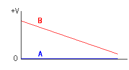 When making temperature setting maximum when there is not this resistor, the positive terminal of the comparator becomes 0 V. Therefore, until the output voltage of the voltage converter becomes 0 V, the relay doesn't work. At the circuit this time, the output voltage of the voltage converter doesn't become 0 V. Because it is, after never, the relay works. When a maximum temperature is guarded with the other equipment, this resistor isn't needed. When there is not a limitation receptacle, a resistor is needed so as not to become above the upper limit temperature. You consider a maximum temperature and must fix an appropriate resistance value. 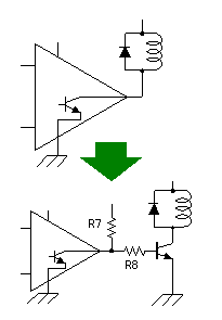 The output of the comparator is an open collector(Type which supplies a power supply to the collector from outside). In case of LM319, the maximum permission loss electric power of the built-in transistor is 500 mW. Because it is, the small relay can be directly driven. The circuit this time isn't doing to the such circuit. However, I changed into the drive circuit which used a transistor because it was unstable that the relay works. It wasn't worked when it should work. When the output of the comparator is ON(It detects below the setting temperature), the base of the drive transistor becomes grounding voltage approximately. Therefore, the electric current doesn't flow through the base of the drive transistor and the transistor becomes OFF condition. The relay doesn't work. When the output of the comparator is OFF(It detects above the setting temperature), the electric current flows through R7 and R8 into the base of the drive transistor and the transistor becomes ON condition. The relay works. When not using an drive transistor, the operating state of the relay becomes opposite. |