Circuit explanation
for +5V Switching regulator (1)
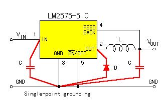
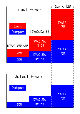 The 3 terminal regulator like LM317 is called the linear regulator or the series regulator. As for the regulator of this type, the output current and the input electric current are the same approximately. Because it is, the difference between the input electric power (The input voltage x The input electric current) and the output power (The output voltage x The output current) is consumed as the heat with the regulator. The figure on the left shows rate of the output and the loss when the input voltage is 12 V, the output voltage is 5 V and the output current is 0.25 A, 0.5 A and 1 A. About 58% of the input electric power is consumed with the regulator as the heat. Therefore, the quite big heatsink must be put to the regulator. 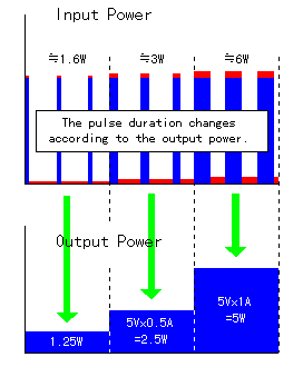 The switching regulator outputs the input electric power as the pulse by the switching operation. The width of the pulse changes by the electric power which the output needs. When the output power is small, the pulse duration is narrow and when the output power is big, the pulse duration gets widely. Actually, it isn't detecting the output power. It is controlling the pulse duration for the output voltage to become constant. The switching regulator doesn't consume the electric power which can not be output like the linear regulator as the heat. Because it is, the big heatsink like the linear regulator is unnecessary. In the specification, the efficiency when passing the output current by 1 A at the input voltage of 12 V becomes 77%. In this case, 1.5 W are consumed with the regulator. Because the input electric power is 6 W when I measure, the consumption electric power of the regulator is 1 W. Because it is, the efficiency becomes 83%. In case of the linear regulator, 7 W are consumed in the condition to be the same. 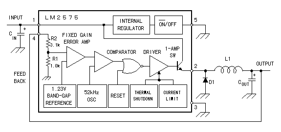 It has the oscillation circuit for the 52-kHz switching. As the reference voltage to keep the voltage constant, 1.23 V are used. It is controlling the pulse duration than the reference voltage and the output voltage. Besides, the extraordinary temperature detector, the output current limitation circuit and so on, too, are had. It becomes the standby condition (the output stop) when adding +5 V to the 5th pin. In this case, the input electric current becomes 50ľA and the low consumption electric power. In case of the switching regulator, the ripple filter circuit with the output voltage is indispensable. Because it switches at the high frequency, you must consider the characteristic of the coil, the diode and the capacitor. I explain how the ripple filter circuit works below. 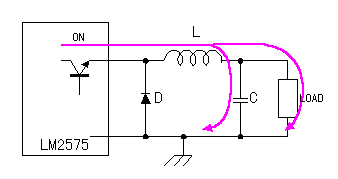 When the transistor of the regulator becomes ON, the electric current flows through the inductor(L), the capacitor(C) and load. The electrical energy is stored up in the inductor and the capacitor. 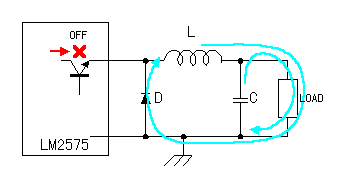 When the transistor of the regulator becomes OFF, the electric current continues to spread throughout the load with the electrical energy which was stored up at the inductor and the capacitor. The electrical energy which was stored up in the inductor flows through the diode(D). In case of LM2575, the switching frequency is 52 kHz. Because it is, as the diode, it uses the shottky barrier diode or the first recovery diode with the short recovery time. This diode to use with the switching regulator is sometimes called the fly-wheel diode. Even if the opposite voltage is suddenly applied in the condition that the forward direction electric current is flowing through the diode, for a while, the electric current flows. At the time of this condition, the rectification operation isn't done and is the same as the copper wire. The time which does the function as the diode (The function to prevent the electric current for oppositely) from this condition is the reverse recovery time. When doing the high-speed switching, this characteristic is very important. When the diode becomes the ON condition(The condition that the energy of the inductor is flowing through the diode) when the switching transistor becomes ON from OFF, the energy from the switching transistor flows through the grounding and doesn't flow through the output circuit. 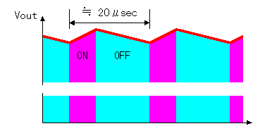 The voltage which is applied to the load becomes like the figure on the left. In this figure, I am picturing the ripple exaggeratedly. When I measure,it is as about 70 mV(1.4%). The voltage of this ripple depends on the inductor and the capacity of the capacitor. The charging current and the discharge current flow through the capacitor. Because it is, it uses the capacitor of small ESR(Equivalent Series Resistance) to make the ripple little. The switching regulator switches over at the high frequency. So, you need following attention to suppress the influence over outside as much as possible.
|
||||||||||||||||||||||||
