+12V/-12V Power supply unit
 |
|
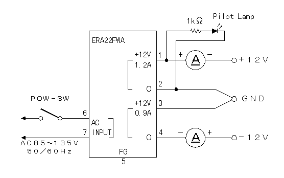
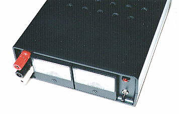
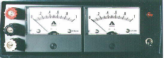
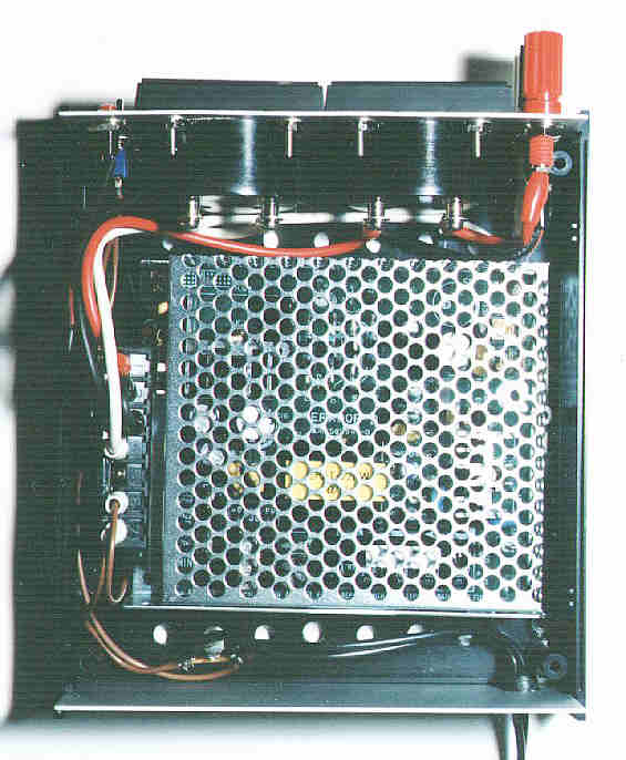
To work the circuit which used the operational amplifier and so on, the positive and the negative power supply become necessary. The power supply which I introduce here is the one to have used the unit which has the two power supplies of 12 V in the one unit. The power supply unit is using the ready-made. It inputs AC100 V and it is possible to take out 12 V of the two DCs which are independent as the output. I considered and made the use (for the experiment) in the future the one with the a little big output current capacity. The positive power supply is the 1.2 amperes and the negative power supply is the 0.9 amperes. I used ERA22FWA of the POWER SOURCE company as the power supply unit.  I am installing the power supply switch and the output terminal in the surface, considering the operability. I opened some holes for the ventilation at the top and the bottom of the case. The size of the case is the height: 56 mm, the width: 150 mm, the depth: 190 mm. (It contains the umbo)  The ammeter used the 1 ampere. The right is for +12 V and the left is for -12 V. I put the mark later so as not to forget. I used the small one as the power supply switch. It is because the switch isn't carelessly touched.  I used the a little thick wire for the side of the output. |