Operation explanation
of the sine wave oscillator
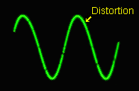
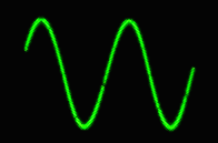
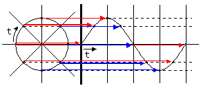 It returns to the original place when going around the circle. At present, it uses the unit, the hertz (Hz), to show the frequency. It was using the word, the cycle per second, before as the unit which shows the frequency. This shows the 1-second number of rotations.(The once is the 1 cycle) The many turns occur in the high frequency. With the figure on the left, 0V There is "a period" in the word which is related with the frequency. This is the time which the 1 cycle takes. It becomes the frequency reciprocal. Period(T) = 1 / Frequency(F) and Frequency(F) = 1 / Period(T) In case of Japan, the electricity to be using in the home is 50 Hz or 60 Hz. In case of 50 Hz, the 1-cycle sine wave occurs the 50 times for the 1 second. 60 Hz are the 60 times. Because it is, the 1 period becomes 1/50 = 0.02 seconds (the 20 milliseconds). In case of 60 Hz, it is the 16.67 millisecond. There is a way of making make the Lissajous as the way of understanding that the sine wave relates to the circle. In case of the sine wave which doesn't have the distortion, the Lissajous becomes the true circle.
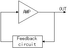
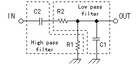
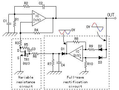
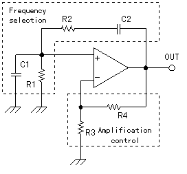 The part which is composed of C1, C2, R1, R2 becomes the positive feedback circuit of the operational amplifier. With it, the operational amplifier works in the oscillation. Also, the circuit sets the oscillation frequency in the damping time constant of the CR. On the other hand, the circuit of R3, R4 controls the mu factor of the operational amplifier. This oscillator begins the oscillation when it makes the mu factor equal to or more than 3. At less than 3, it doesn't oscillate. The beautiful signal doesn't come out by output's being saturated when the mu factor is more than 3. The mu factor must be controlled to 3. Because it is, only this basic circuit can not use for the practical use. 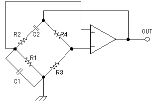 The balance condition of this bridge becomes the oscillation condition. The oscillation frequency can be calculated by the following formula.  In case of C=C1=C2, R=R1=R2, the formula becomes the following.  The condition of the operational amplifier which is necessary to do the stable oscillation is the mu factor=3. It becomes the following when finding the relation between R3 and R4 from the mu factor.(Noninverting Gain amplification) 3=(1+R4/R3) That is, the condition of R4=2xR3 is necessary. The circuit composition of the positive feedback circuit becomes like the left. You find that the composition of this circuit is composed of the low pass filter and the high pass filter. The low pass filter make pass the low frequency signal and blocks the high frequency signal. The signal flows through the grounding with C1 and the output voltage becomes low when the frequency becomes high. Oppositely, the high pass filter make pass the high frequency signal and blocks the low frequency signal. It is because the signal which passes C2 becomes little when the frequency becomes low. 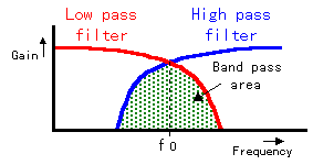 When combining these two, the signal in the area that the characteristic is the overlapping frequency gets to pass. Such a filter is called the band pass filter. When combining these two, the signal in the area that the characteristic is the overlapping frequency gets to pass. Such a filter is called the band pass filter.
There are various circuits from the simple one to the complicated one. The circuit to be using this time changes the resistance value of the Field Effect-type Transistor(FET) at the d.c. voltage which rectified the oscillation output in the full wave. 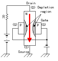 The electric current of the controlled circuit flows from the drain terminal of the semiconductor on the N-channel to the source terminal. The semiconductor on the P channel is used for the gate. When the negative voltage is gained by the gate terminal, the electron on the N-channel(it has the negative electric charge) repels and can make the depletion region to be the junction part with the P channel. Because the electron doesn't exist in the depletion region, the electric current doesn't flow. When the voltage which is gained by the gate isn't high, the depletion region is small and the flow of the drain electric current isn't too much influenced. 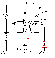 Therefore, as for the drain electric current, the place to flow through becomes narrow and the electric current decreases. Because it is, by changing the voltage to add to the gate, the drain electric current can be controlled. The big characteristic of the FET is the fact that the electric current doesn't flow through the gate. It is possible to control only at the voltage of the gate. The electric power(current X voltage) isn't necessary in spite of the control. This operation resembles the operation of the tube well. The circuit to compose in IC(2/2) is the full-wave rectification circuit. When the output voltage of the oscillator is the positive voltage, the signal spreads through the negative input terminal of IC(2/2) through D2. At the positive input terminal, it is prevented by D3 and the signal doesn't spread. At this time, IC(2/2) does the inverting gain amplification. Because it is, the output of IC(2/2) becomes the negative voltage. Next, when the output voltage of the oscillator is the negative voltage, the signal spreads through the positive input terminal of IC(2/2) through D3. At the negative input terminal, it is prevented by D2 and the signal doesn't spread. At this time, IC(2/2) does the noninverting gain amplification. Because it is, the output of IC(2/2) becomes the negative voltage too. In this way, the voltage which is always negative is output by IC(2/2). Because the output of IC(2/2) is the ripple current, there is a smoothing in R7 and C4 through D1 and it makes the total direct current. The d.c. voltage by the full-wave rectification circuit changes in the change of the output voltage of IC(1/2). The d.c. voltage which was made by the full-wave rectification circuit is added to the gate of TR1(FET) through R6. The negative voltage which is gained by the gate of TR1 becomes high when the output signal of IC(1/2) becomes big. Then, the resistance value between the drain and the source of TR1, too, becomes high. The mu factor of IC(1/2) falls when the resistance value of R3 and TR1 which is stored in series becomes high. The output of IC(1/2) is restrained by it. R5 and C3 improve the frequency characteristic of TR1. It makes the distortion of the oscillation signal by TR1 little.
|
|||||||||||||||||||||
