Digital dial
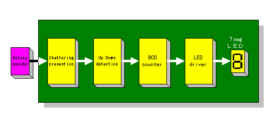
 Block diagram of the top is a clickable image map.
You can jump to each page of the explanation when you click each block. |
|
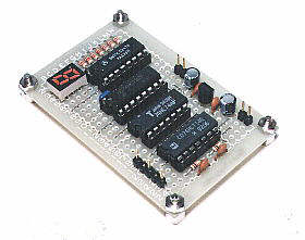
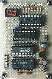
This circuit is the up down circuit of the digital counter which used a rotary encoder. Two sliding switches are incorporated into the rotary encoder. The timing that each switch closes is shifted. Because this circuit detects the timing that each switch closes, it judges the clockwise(CW) or the counterclockwise(CCW) of the switch, and adds or subtracts a counter. It is possible to do application when turning a dial and setting a digital value.
|
 |
|
 |  |