Circuit explanation for Remote Door Lock
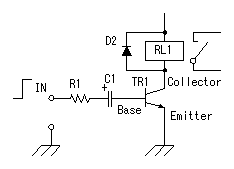
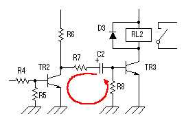
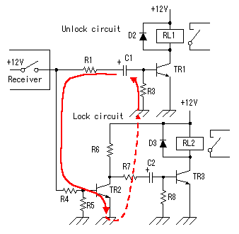
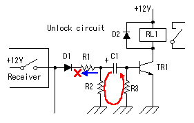
 The basic circuit to use this time is a circuit on the left. The electric current flows like R1 -> C1 -> Base of TR1 -> Emitter of TR1 -> Ground when the voltage of input(IN) changes from 0V to +12V. The store of the electric charge to capacitor C1 begins with this electric current. Because voltage of the both edges of the capacitor goes up when an electric charge is stored up into the capacitor, the electric current decreases. The decrease of the electric current is due to the following reason. When the voltage between the IN and the ground is 12V, the electric current which flows through resistor R1 becomes the value which divided the voltage which is applied to the resistor by the resistance value. For example, when an electric charge isn't stored up in C1, the voltage of C1 is 0V and the voltage which is applied to R1 becomes approximately 12V. Strictly, this value becomes the values which are about 0.6V few. 0.6V is voltage between the base and the emitter. In this explanation, I ignore this value. Supposing that the resistance value is 3.3 k-ohm, the electric current which flows through the resistor is 12V/3300ohm = 0.0036A = 3.6mA. As an electric charge is stored up into C1, the voltage of C1 rises. For example, it supposes that the voltage of C1 rose to 5V. In this case, the voltage which is applied to the resistor becomes 12V-5V = 7V. So, the electric current which flows through the resistor becomes 7V/3300ohm = 0.0021A = 2.1mA and is decreased compared with the previous value. Finally, when the store of the electric charge ends in C1, the electric current which flows through C1 stops. Next, I let's explain that the transistor works. As for the transistor, when the electric current is flowing through the base, the electric current flows through the emitter from the collector. So, in case of being in the condition which the electric charge is storing up in C1, the electric current flows through the base and the relay (RL1) works. The electric charge finishes being stored up into C1 and the base electric current stops, the collector electric current gets not to flow and the operation of the relay (RL1) stops. That is, even if 12V are continuously applied on input (IN), the relay (RL1) works only in the constant time. Next, I let's explain the calculation of the value of R1. The value of R1 is decided by the base electric current. The transistor has current amplification factor (hFE). The collector electric current with the value which multiple hFE on the base electric current can be passed. This is the value not to flow through the collector by and for it to be able to pour. For example, it assumes the transistor's hFE is 100. When making R1 3.3 k-ohm and in case of electric charge's not being stored up yet in C1, (12V-0.6V)/3300ohm = 0.0035A = 3.5mA is a base electric current. When hFE is 100, the collector electric current is 350mA. However, the electric current which flows through the collector is decided by the circuit which is connected with the collector. This time, because the collector electric current flows through the relay (RL1), more collector electric currents don't flow than the electric current which flows through RL1. Actually, only the about 30mA electric current flows through RL1. So, even if the 3.5mA electric current flows through the base, the collector electric current is 30mA. Seemed a base electric current for it as extra but this is to make a transistor ON condition perfectly. The transistor doesn't become ON condition perfectly in case of being a base electric current (30mA/100=0.3mA) as the calculation and the resistance occurs between the collector and the emitter. In this case, extra electric power is consumed with the transistor. In the time that the relay (RL1) works, it is decided by the value of capacitor C1. It is difficult to calculate this value. It is possible to calculate, but the actually tried one is simpler and is sure. Decide the operating time of the relay while changing the value of the capacitor. The timer circuit is using the time that an electric charge is stored up into the capacitor. When not discharging the electric charge which was stored up in the capacitor, the timer circuit doesn't work, being normal at the next time. The circuit to make discharge the electric charge which was stored up in the capacitor is necessary when the input passed away.  The figure on the left is the door lock circuit. When TR2 is in the OFF condition, the electric current flows through R6 -> R7 -> C2 -> TR3, and C2 charges. Next, when TR2 becomes ON condition, the electric charge which was stored up in C2 flows through R7 -> TR2 -> Ground -> R8 and discharge by it. In case of the NPN transistor, because the electric current doesn't flow the base from the emitter, it needs R8. You can connect the collector of transistor TR2 with the node of C2 and R7 without dividing R6 and R7. The way can quicken to discharge of the capacitor. The circuit this time divided R6 and R7 to suppress the discharge current of C2. However, because there is R8, there is no need for division. This door lock circuit differs compared with the previous basic circuit in the condition of the input. The relay works only in the constant time when the input falls to 0V from +12V. TR2 is doing the function of the inverter.  The schematic on the left is removed D1 and R2 from the door unlock circuit. In this case, when the switch on the receiver is turned off, the electric charge which was stored up in C1 flows through R1 -> R4 -> TR2 -> Ground -> R3. Therefore, TR2 doesn't become OFF condition immediately and the operation of the relay (RL2) becomes slow. Moreover, because the electric currents which flow through C2 are few, the operation of the relay (RL2) becomes weak. The normal operation can not be gotten.  When adding D1 and R2, the discharge current of C1 flows through R2 -> Ground -> R3 and doesn't flow through the door lock circuit. With this, the door lock circuit can be worked, being normal. |